Inductor EM simulation: 1-port or 2-port?

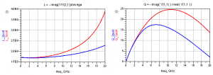
How to simulate RFIC inductors, as 1-port or 2-port EM models? Why do we get different results for the Q factor, and which is right?

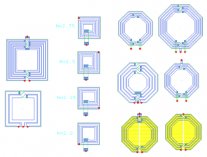
When EM simulating on-chip inductors, it is not obvious which port configuration is “best”. Depending on the port configuration, the extracted inductor properties can be very different. In this document, we will review the different configurations, and find out what is most suited for parameter extraction and modelling.

Inductor EM simulation: 1-port or 2-port?

Muehlhaus Inductor Toolkit now supports SBC18H technology


Muehlhaus Inductor Toolkit for ADS is now available for the TowerJazz SBC18H family of technologies. EM Substrate files have been verified against measured inductors.

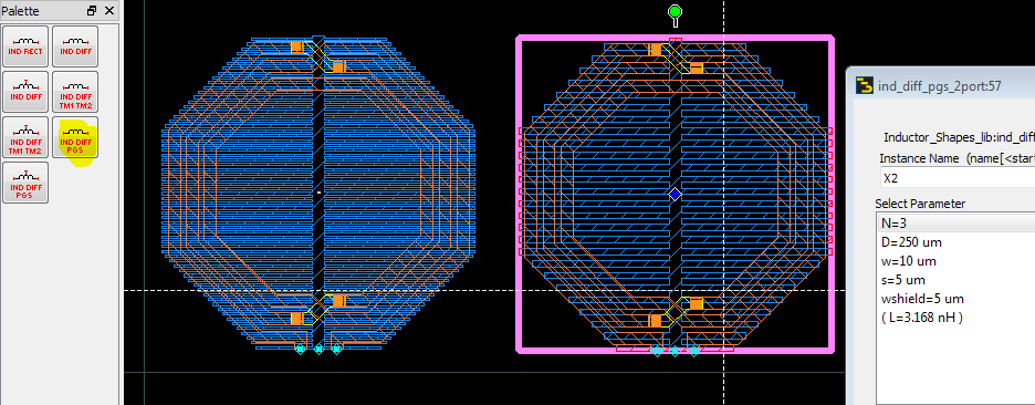
In addition to the standard inductor layouts from Inductor Toolkit, more layout options are provided that match inductor pcells in the SBC18H3 PDK. This enables an additional usage model: users can calculate the optimum inductor parameters (dimensions) with Muehlhaus Inductor Toolkit for ADS, and then in their Cadence or ADS workflow use the original TowerJazz pcells with those optimum parameters.


About Muehlhaus Inductor Toolkit…


Merging via arrays in ADS 2012

Via arrays

In RFIC, larger vias are created as via arrays. The size of each single via is usually fixed by the technology rules, and via arrays are created where a larger via cross section is needed. This application note describes efficient modelling of via arrays in Agilent ADS with the Momentum EM solver.
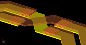
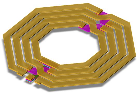
via array in planar inductor

(click for full size)

Via arrays consist of many parallel conductors in z-direction, where no current can flow in the x-y plane. That’s a difference between via arrays and the solid via blocks (“via bar”, “slot via”) that are also available in some technologies: a solid via can also take horizontal current, but the via array can only take vertical current. This difference is important when metal layers are stacked with vias: the via array does not add cross section for the horizontal current flow, but a solid via does. Why do we care? Because that’s the behaviour of via arrays vs. solid vias in the real world, and we need to be carefuly with any via simplification that might change this current flow. This is discussed at the end of this application note.

Via simplification by merging

Via simplification is usually done by combining the individual vias into a larger polygon that follows the outer boundary (or bounding box) of the via array. We will first discuss different ways how this merging can be done, and later deal with the errors and side effects of that approach.

Merging with an AEL script

The vias of an array can be merged by a series of oversize – merge – undersize commands: First, the size of each via is increased, until they overlap. Then, the overlapping shapes are merged, and finally the merged shape is undersized again, so that we get back to the original outline. This can be automated by an AEL script, as shown here:

[box]defun viamerge()
{
decl context = de_get_current_design_context();

// select everything on via layers
decl layerId = db_find_layerid_by_name(context,”contact:drawing”);
db_select_all_on_layerid(context, layerId, TRUE);
layerId = db_find_layerid_by_name(context,”via1:drawing”);
db_select_all_on_layerid(context, layerId, TRUE);
layerId = db_find_layerid_by_name(context,”via2:drawing”);
db_select_all_on_layerid(context, layerId, TRUE);

// oversize by 2 microns
de_set_oversize(2, 0);
de_oversize(1);
// combine shapes
de_union();
// undersize by 2 microns
de_set_oversize(-2, 0);
de_oversize(1);

de_deselect_all();
context = NULL;
}[/box]

The script is placed in the workspace directory, loaded from the ADS main windows and applied to a layout from the ADS command line. Obviously, the script needs to be adjusted for different via sizes and layer names.
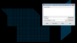
Via merging from the command line with AEL script

(click for full size)

Implemented as above, the script is destructive: It replaces the via array by the merged shape, on the same layer.
Diagonal stepped vias create a staircase boundary. Vias with a spacing larger than the oversize value are not merged.
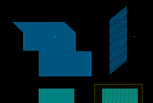
(click for full size)

What values should we use for oversize/undersize? Depending on the foundry and PDK implementation,  there are subtle differences how Pcells generate via arrays with a given target size that doesn’t match exactly with n*viasize + (n-1)*viaspacing. The viasize or viaspacing might be slightly increased to match the total dimension. This is relevant for via simplification algorithms that are based on exact viasize and viaspacing values: better add some tolerance to handle these cases, i.e. used larger values for oversize/undersize, within reasonable limits. Too large values might create false connections (short circuit) between adjacent via arrays.

Via simplification by ADS 2012 derived layers

In ADS 2012.08, Agilent introduced the derived layer function “grow envelope” that we can use for via merging. But before we look at the actual implementation, let’s review the derived layer concept.

[pullquote align=right]If derived layers are not preconfigured in the PDK, no problem: The user can add them to his library where he has read/write access. [/pullquote] Derived layers is a new concept for layout preprocessing for EM which was introduced in ADS2011. Each derived layer takes some input information from one or more source layers, and performs some operations on the shapes found on these layers. This can be boolean operations or sizing, for example. The resulting new shapes are then written to the derived layer, without touching the original shapes on the source layers. So this is non-destructive, whereas our AEL-based via merging above was destructive and replaced the via arrays with the merged shapes. Besides beeing non-distructive, the “grow envelope” method also creates nicer diagonal shapes instead of the staircase pattern shown above.

Grow envope is new in ADS 2012.08. The only input parameters are the source layer and the desired growth. The word growth is misleading here, because the final shape has the correct boundary size and does not grow. Growth is only a temporary step for merging the shapes.
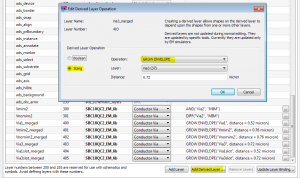
Adding a derived layer for via merging

(click for full size)

What values should we use for growth? Depending on the foundry and PDK implementation,  there are subtle differences how Pcells generate via arrays with a given target size that doesn’t match exactly with n*viasize + (n-1)*viaspacing. The viasize or viaspacing might be slightly increased to match the total dimension. This is relevant for via simplification algorithms that are based on exact viasize and viaspacing values: better add some tolerance to handle these cases, i.e. used larger values for oversize/undersize, within reasonable limits. Too large values might create false connections (short circuit) between adjacent via arrays.

[pullquote align=right]Derived layers are only visible to the EM simulator. You can see them in 3D EM preview, but not in the layout editor![/pullquote]How to check the outcome of the derived layer operation?
If you look at the layout editor, you will only see the original geometries, but no shapes from derived layers. Derived layers are only visible to the EM simulator, and shapes on derived layers are only created during the pre-processing phase of an EM simulation.
To actually use the shapes from the derived layers, map the derived layer in your EM substrate instead of the original source layer. That’s all you need to do.

Note that creating the derived layer shapes is a preprocessing step that must be enabled in the Preprocessing options (enabled by default). You can also force an update of the derived layer content without running the full simulation: at the bottom right of the emSetup dialog, you can choose what you want to generate. By default, that is set to “S-parameters”, but you could set it to “Pre-processed geometries” to run that step only. Only if you do this, then you will see the derived shapes in the layout editor.
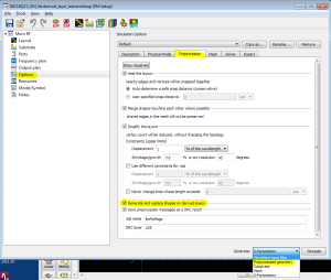
Preprocessing settings to create derived layer shapes

(click for full size)

Now that we understand derived layers, we can apply this to via merging. The “grow envelope” function is perfect to calculate the via array’s boundary, and the resulting shapes on the derived layer can be mapped in the EM substrate instead of the original via geometries. The EM preview will then show the merged via boundary if things are configured properly (and if the via array is not merged properly, it will take forever to visualize the 3D model with thousands of individual vias …)
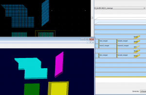
EM preview with derived layer

(click for full size)

Simulation accuracy: Side effects on via loss and Q factor

The big question is: the simulation is much faster with merged vias, but how accurate is it? There are different aspects that need to be considered.

Direction of current flow

In the beginning of this application note, we had discussed the different current flow in via arrays (vertical current only) versus solid via blocks (current can flow in any direction). By merging the via array into one solid via, we have changed the possible current flow from vertical (z-axis) to arbitrary (x,y,z). This is not a big deal for vias as shown above, but it does matter for wide via arrays in stacked conductor configurations.
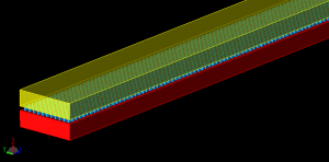
metals stacked with via array

(click for full size)

The original via array with its z-only current does not carry horizontal (x-y) current, so that the effective cross section of stacked metals is defined by the metal itself. If we now merge this via array to a solid via block, this changes the effective cross section of the line, by adding the via metal as an additional parallel conductor that can carry horizontal current. This is where the Momentum setting for via currents (2-D distributed or 3-D distributed) becomes relevant.
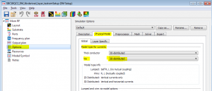
Via physical model 3D or 2D

(click for full size)

By default, that setting defaults to 3-D distributed, which means that vias can carry current in all directions, including horizontal (x-y) currents. Again: we don’t wory much about small via arrays, but for large via arrays in stacked metal configurations, you want to set this to 2-D distributed if the true shape of that vias is an array. This prevents x-y current on the via that does not physically exist in the manufactured hardware. In case of doubt, double check with a simple testcase to see the effect.

Note that this settings will affect all vias in the simulation model. You could also make a choice per layer, but you can not change this setting per polygon.

If the physical via in the hardware is a solid block (“via bar”, “slot via”) that can carry horizontal current, then 3-D distributed is the correct choice. These solid vias are quite rare, but they exist in some RF-optimized technologies. They are typically on other layers than the via arrays, so that the per-layer setting for 2-D/3-D can be applied.

Effective size/cross section of the via

Another obvious effect of via merging is that we change the effective conductor cross section of the via: we now have the boundary fully filled with metal, where the original array was only partially filled with metal. The typical “fill factor” of an array is around 25%. By merging the vias into one solid block, we now have 100% fill factor. This reduces the via resistance in z-direction. [pullquote align=right]Our license agreement with Agilent does not permit to perform and publish benchmarks, so you need to run testcases yourself, if you want to be very accurate on via loss modelling.[/pullquote]
If we are interested only in the correct DC resistance, we could compensate for that error by lowering the conductivity. This is what Sonnet’s via merging internally does. However, due to skin effect, the current pushes to the outside vias, away from the inner part of the via (array). Skin effect depends on conductivity, and compensating an incorrect fill factor with a change in conductivity will then change skin effect and so on … Not obvious what the best approach would be.In most cases, the contribution from via resistance is really small, and most conductor loss is from the planar metals anyway. But in case of doubt, just set up a few simple test cases.



EM Tech File Editor m/matl now supports ADS 2011

EM Tech File Editor m/matl now supports ADS 2011

[two-thirds]

We have extended the m/matl EM Technology File Editor to read and write ADS 2011 *.subst files.

Important: This ADS 2011 substrate file format uses a shared material database file. Please see the documentation for detailed information on writing and coyping *.subst files.

Go to m/matl product page for download

[/two-thirds] [third]   [/third]


End of software reseller business, new focus on EDA consulting

End of software reseller activity, new focus on pure-play consulting

Effective 31. Dec 2012, we have terminated our reseller agreements with Sonnet Software Inc. and IMST GmbH, and switched to a new business model which is entirely focused on RF EDA consulting services. We would like to thank all our customers, and our friends at Sonnet Software Inc. and IMST GmbH, for many years of good and trusted collaboration. The new Sonnet reseller advico microelectronics will take over all business and support activities as of 1. January 2013.

We apologize for the inconvenience that this change might cause. For Sonnet customers with update & support service ordered through Mühlhaus, we will be available for support questions until the end of the current support period, but no later than 31. October 2013. At any time, these customers might also switch to Sonnet USA support, or support from the new representative advico, at their discretion.


m/matl Technology File Editor – New Release

[two-thirds]

A new release of the m/matl EM Technology File Editor is now available.

New features:

  • Import of technology information from Cadence Assura procfiles
  • Export to Empire XCcell 3D EM
  • Export to Asitic tek file (beta)

For more information and download, click here.

Import from Cadence Assura procfiles

You can import substrate information from existing Cadence Assura procfiles.

To use this option, use File > Import and select an Assura procfile. The software will evaluate the procfile, and also try to find and evaluate two additional files in the same directory: p2lvsfile and lvsfile. If these additional files are not available, the via information is missing and you need to set the via layout (from… to …) manually.

Unfortunatly, the layer names used in the Assura files do not always agree with the layer names used in the layout editor. During import, m/matl tries to figure out the layer names, as best as it can. Sometimes, this is not possible and you need to set the correct Cadence layer names manually.

Important limitations for using Assura procfile import:

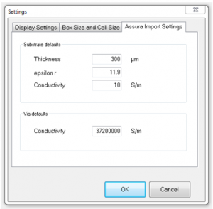
It is important to understand that the substrate itself is not included in any of these files. The substrate thickness, permittivity and conductivity are added based on m/matl default values. These default values can be set with File > Preference > Assura Import Settings.

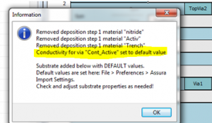
In this dialog, there is also a settings for via conductivity. The via conductivity might be defined in the Assura files, or it might be missing. If the information is missing, the default will be used and this default assigment is listed in the import summary message.

Another note in the import summary message is related to the deposition steps. At the surface of the substrate, there are multiple deposition steps 1 defined, for different areas of the chip. The m/matl import uses only the first line for deposition step 1, which is usually for field oxide, and skips the other deposition step 1 entries. These skipped lines are listed in the import summary message.

For metal sheet resistance specified in the p2lvsfile as (Ri,wi) pairs for width dependent sheet resistance, m/matl uses the last entry, which is supposed to be valid for widest metal traces.[1]

Carefully check your results! The Assura import has been tested and optimized with many different design kits. However, there is some “educated guess” required in some cases, especially for layer names. If you experience problems, please let us know!

[/two-thirds]

[third]   [/third]


[1] From the Assura documentation: “Additionally, the (ri,wi) pairs should be specified in order of increasing width.”

Sonnet Verification Kit for TowerJazz SBC18H


[two-thirds]

Dr. Mühlhaus Consulting & Software GmbH has now released Sonnet Verification Kit for TowerJazz SBC18H

This new Sonnet verification kit is designed for simulation of passive components such as inductors and transformers in the TowerJazz SBC18H process family including SBC18HA, SBC18HX, SBC18H2 and SBC18H3 amongst others. The definitions for the Sonnet model file of conductivity, permittivity, dielectric and conductor thicknesses are current with the TowerJazz Process Specification NPB-PS-0267 rev17.

The Sonnet files apply to all SBC18H processes with 2.81um thick Al top metal and identical interconnect stackup as SBC18HX. The S-parameter measurements and GDSII layout data for the inductors used in this work were provided by TowerJazz.

The Sonnet Verification Kit is available to TowerJazz customers from the TowerJazz eBizz website, section “Special Tools”.

[/two-thirds]

[third]    [/third]


EMPIRE XCcel 6.00: New Thermal Solver

New Thermal Solver

[two-thirds]

With its new release, the well‐known 3D EM solver EMPIRE XCcel now features a novel thermal solver for the simulation of the temperature distribution of power electronics, RF circuits, integrated circuits and also including electromagnetic heating in human bodies.

The thermal simulation includes thermal conductivities of materials, surface convection and radiation cooling and supports heat sources and heat sinks for heating and cooling mechanisms.

With increasing packaging density of RF circuits heating can become a severe problem for the lifetime of critical components such as diodes (also LEDs), transistors, resistors, and ICs. Also passive structures such as filters, couplers or resonators can exhibit high currents in small areas where the temperature can rise to a critical level. In case of electromagnetic radiation the prediction of thermal heating inside of human bodies (e.g. handheld antenna attached to human head) is necessary to prevent hazards.

Figure 1: LTCC module with LEDs and driver circuit (click to view full size)

Figure 2: Temperature distribution on the LTCC module (click to view full size)

The accurate prediction of the temperature distribution is now possible with EMPIRE XCcel 6.00. The structure is created within the GUI where properties such as thermal conductivity and heat transfer rates can be entered similar as the electromagnetic properties. A large database is already equipped with known parameters. Thermal sources can be set directly, e.g. by entering a thermal power in Watt for a lumped element such a transistor. Thermal sources can be determined by an EM simulation, too. With a combined EM and Thermal simulation the RF losses are calculated in a first EM simulation run and will be used as a source for a subsequent thermal simulation. Cooling elements can be defined as surfaces with a specific thermal resistivity. In case of human body thermal modeling also the blood perfusion rate can be taken into account. In addition, known thermal properties are available in a tissue data base.

The simulation engine automatically identifies the surface to air interfaces and invokes the heat transfer mechanisms such as radiation and convection. With this method, cells filled with air don’t need to be part of the solution thus minimizing the number of cells to be simulated for the temperature distribution. A robust and efficient solver kernel is used for the fast solution of the thermal equations. An adaptive scheme optimizes the over‐relaxation factor during the iteration process for maximum simulation speed. After simulation the temperature distribution can be displayed together with the structure. The temperature can be displayed as distinct planes, as maximum or minimum of each plane or as top‐ and bottom side temperature distribution. The latter is especially intended for the comparison with infrared camera pictures.

As an application example an LTCC module is shown in Figure 1 which has been developed in a joint project of the German companies odelo LED GmbH, IGOS GmbH and IMST GmbH and was co‐funded by the German federal state North Rhine Westphalia (NRW) and the European Union (European Regional Development Fund: Investing In Your Future). It contains 3 LED chips on top which are die‐ and wire‐bonded to the top metallization. A small driver circuit with Shottky diode, transistor and resistor is placed on top side, too. Many thermal vias are integrated beneath the active elements to transfer the heat from the topside to the heatsink at the bottom side. In this case the power loss is known and entered as lumped and distributed heat sources.

Figure 2 shows the topside temperature distribution obtained with EMPIRE XCcel 6.00. The module is subdivided into 10.3 million cells and an accuracy of 0.6 mK has been obtained after 2700 iterations. The simulation time needed is about 3 minutes on a Notebook with Intel Core i7‐2620M CPU @ 2.7 GHz. For this size the memory requirement is about 1 GByte. The temperature rise is about 40 K above ambient temperature with the maximum inside the transistor package.

As can be seen a temperature distribution for a complex structure is obtained with EMPIRE XCcel 6.00 which gives valuable input for the thermal design. As known from EMPIRE XCcel’s unique fast FDTD kernel, the new thermal solver has also been optimized with respect to solution speed thus giving reliable results within minimum of solution time.

[/two-thirds]

[third] [/third]