This application note explains two different ways of using layout parameters for Momentum EM simulations:
- Use built-in parameters in layout created from standard circuit elements (microstrip line etc.)
- Parameterize manually drawn layout from rectangles/polygons
We will discuss the use EM results of parameterized blocks in a schematic, with emSetup/emModel views.
A basic understanding of Momentum mesh setup etc. is required. Those details are not discussed again in this document.
EM workflow basics: emSetup, emModel and symbol view
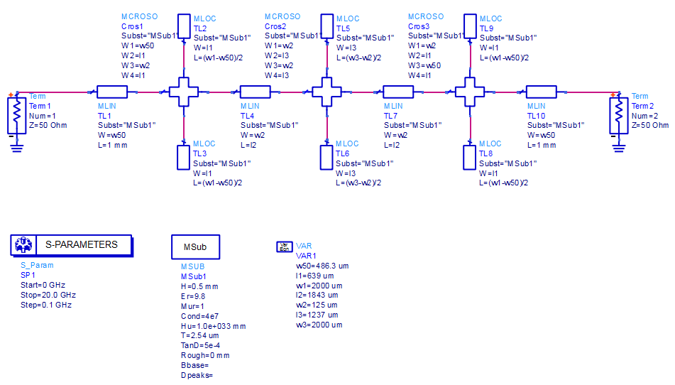
A typical microstrip circuit design workflow in ADS starts from schematic elements with built-in electrical models. This is very fast and efficient if the layout can be created from “building blocks” that ADS provides. Variables that control the element size are defined in the schematic’s VAR block.
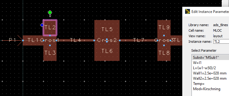
Starting from this schematic, we can easily auto-generate the layout. The layout then consists of ADS elements that all have parameters, and reference the schematic VAR block where variable values are defined.
From this layout, we can easily create an EM model. Before we move on to scalable EM models, let’s see how that (fixed) emModel is created and used.
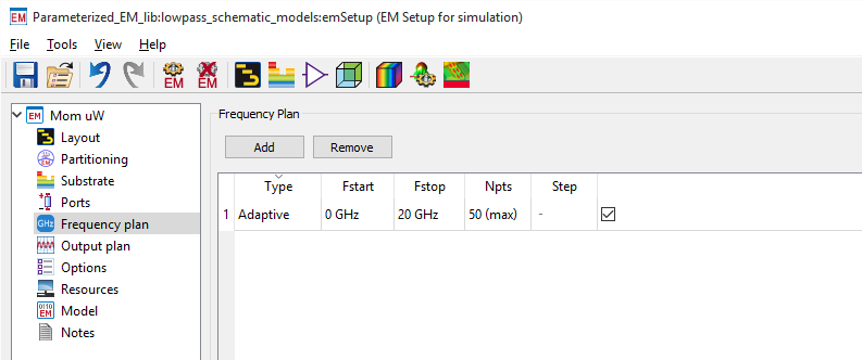
After creating the EM substrate for 500µm Alumina, we can create the emSetup from 0 to 20GHz.
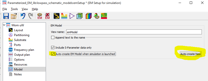
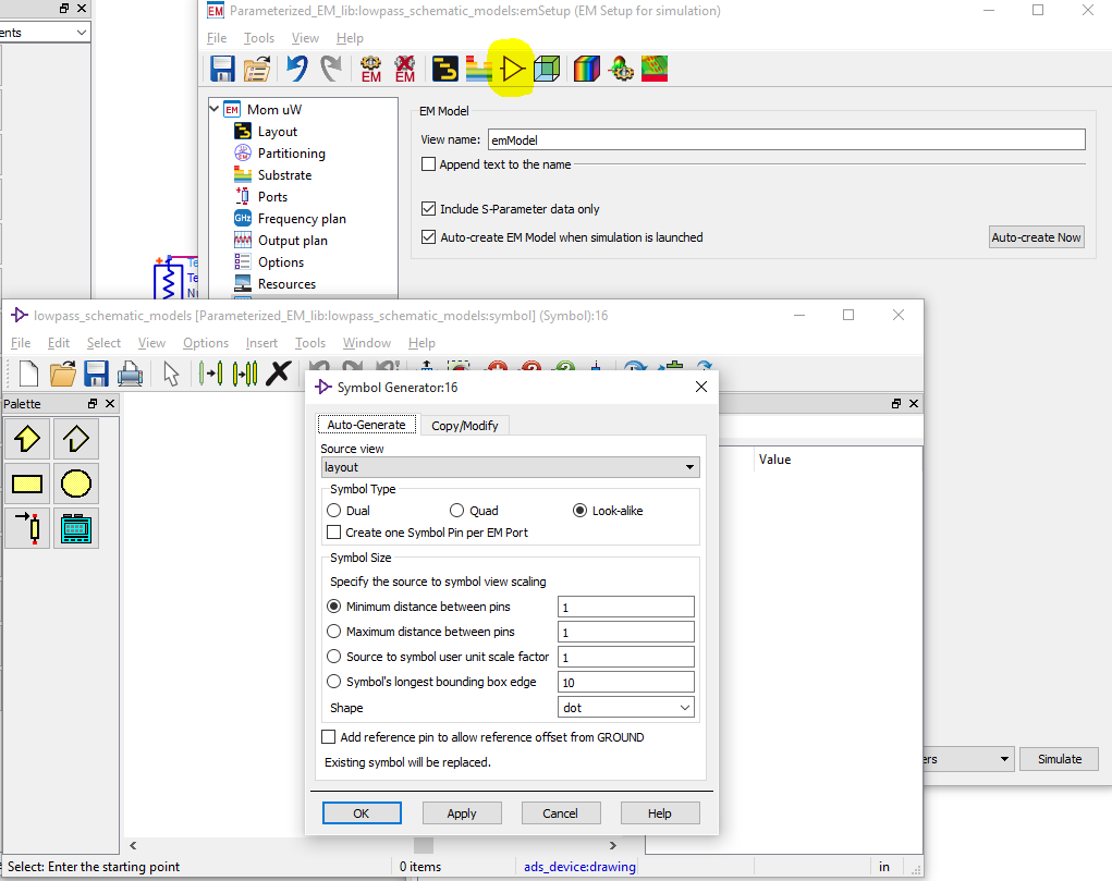
In the Model section of the emSetup, we enable “Auto-create EM model when simulation is launched” and then press the “Auto-create Now” button to create an empty emModel.
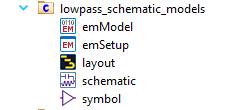
That emModel will show up in the list of cell views, and is the container that holds EM simulation data. When an emModel is called from a schematic, ADS will check if EM results are already avaliable for that (or should we say “in that”?) emModel. If data is not yet available, the Momentum simulation will be started and results will be stored into the emModel.
How can we call the emModel from a schematic? As always, we need a schematic symbol to use a cell in the schematic. This symbol can be created from the emSetup dialog toolbar, using the icon that looks like a buffer.
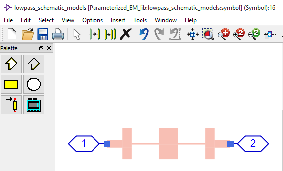
What symbol style you want to create depends on your personal prefences, but the default (layout look-alike) is nice because it shows port locations visually. If we use the symbol generator defaults, we will get this symbol for our lowpass:
That’s it. We now have a cell with schematic view, layout view, emSetup to configure EM simulation, emModel view to store the EM results and a symbol view so that we can place the cell in simulation schematics.
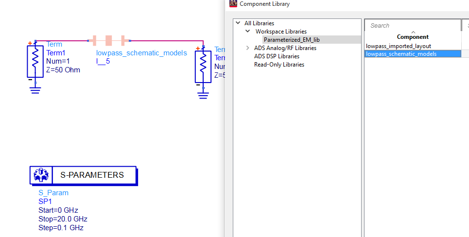
To test this, let’s create a new schematic and then place our lowpass cell symbol by drag & drop from the ADS project tree. You can also use the element browser (Insert > Component > Component Library) if you prefer that.
After the symbol is placed, the schematic can be used for simulation. If the Momentum simulation was already finished earlier, data is retrieved from the emModel almost instantaneously. Otherwise, the Momentum simulation will be started automatically when the schematic simulation needs the data.
When we start schematic simulation, we get an error message like
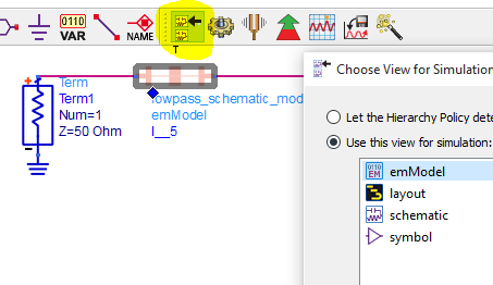
The instance `I__5′ has 2 pins, but the view `Parameterized_EM_lib:lowpass_schematic_models:schematic’ has 0 pins.
because we had placed “Term” elements in the schematic only (for S-parameter simulation) and did not place any hierarchical pins at the input and output. We want to use the EM simulation anway (not schematic), so we need to select the emModel view as the active simulation view.
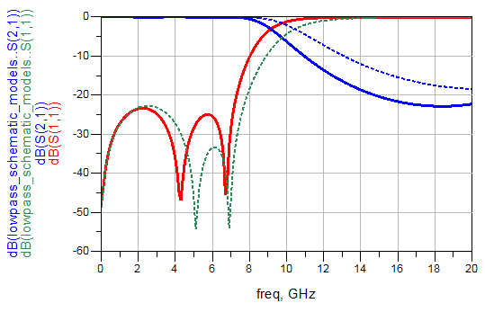
Now we can run the schematic simulation with the EM low pass block and compare it to results from the microstrip line models. At this moment we only have a “static”, fixed EM model without parameters, and you might ask: “What is the benefit compared to normal Momentum simulation?” The answer is: Once we understand this use of emModels for EM-schematic co-simulation, it is easy to add layout parameters.
Layout created from standard elements that already have built-in parameters
Once we understand the “fixed” cell workflow discussed above, it is easy to add layout parameters.
We need to go to File > Design Parameters where we can add parameters for the cell. These parameters are then available inside the cell views for schematic and layout. For our testcase, we remove w3 and l3 from the schematic VAR block, and add them as cell parameters.
If we now place the cell symbol in another schematic, we can see that the cell has two parameters l3 and w3, as defined earlier.
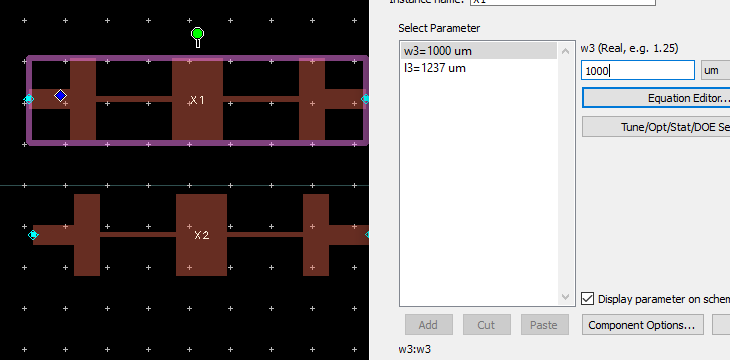
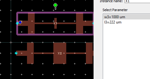
However, if we change these parameters to see what happens, we notice that the layout does not update properly. The best way to see that is to place two instances of the cell, with different parameter values, in one layout.
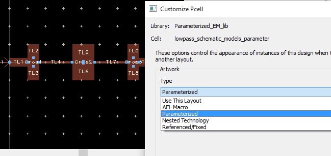
Bug or feature? Not sure what it is, but we need to make one change in ADS so that the cell with parameters does update properly. Solution: In ADS 2015 or later, we need to go to File >Customize Pcell for the layout view ….
… and change the setting from “Use this layout” to “Parameterized“.
[two-thirds][box type=error]By default, ADS layouts are assumed static (fixed) and do NOT update when we add parameters and change their values. For parameterized cells, use menu item File > Customize Pcell and change the setting from “Use This Layout” to “Parametric”.[/box][/two-thirds][third] [/third]
Only with this change, the layout will update properly when cell parameter values are changed!
After making that change, we can see that parameter changes are properly shown in layout. This means our cell parameters work fine now, and teh layout updates properly.
We can now use our parameterized cell for EM co-simulation, in in the same way as we use other parametric elements. For example we can do a simple parameter sweep in schematic:
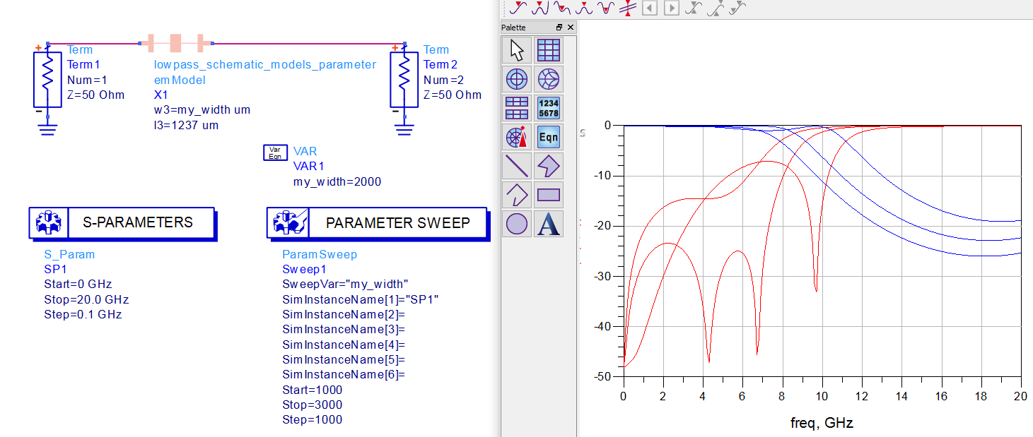
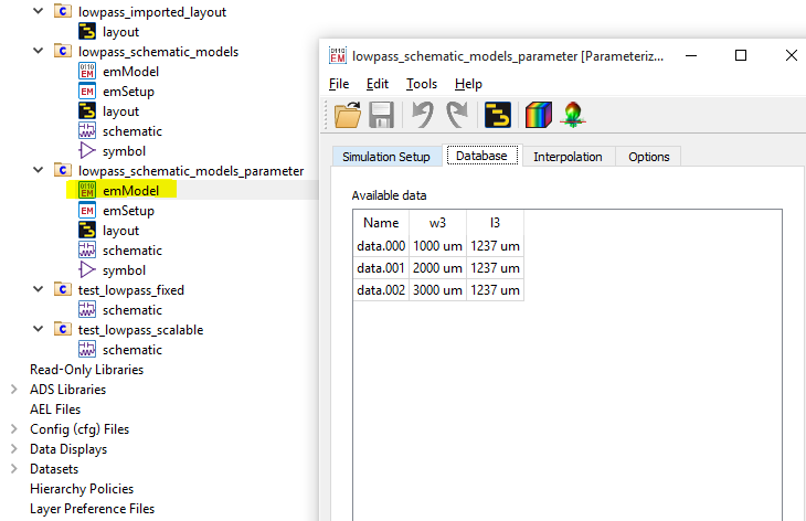
At any time, we can check the emModel and see what data was already simulated and stored for re-use:
That’s it. Co-simulation of parameterized EM layouts should now be easy, as long as they are created from layout building blocks that support parameters. But what about layouts drawn manually, or imported from DXF, GDSII etc? How can we parameterize that for EM? This will be covered in the next chapter.
EM parameters for “drawn layout” from polygons
Layouts that are drawn manually, or imported from DXF/GDSII/Gerber files, do not have parameters. Parameters can be added for EM simulation in a “graphical” way by moving layout edges and declaring the corresponding parameter values. This will be shown below with a simple example.
The layout is the same low pass filter as before, but now drawn from a few simple rectangles instead of parameterized ADS building blocks. We want to scale the width and length of the middle element by cell parameters that we need to add/define now.
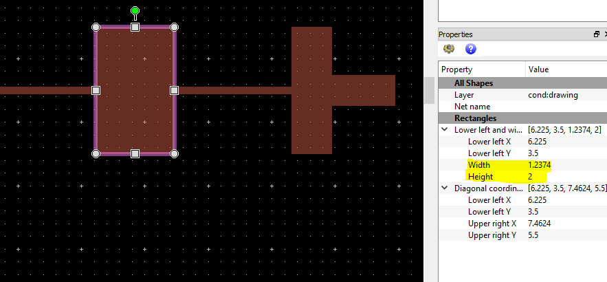
Parameters are added by a pertubation technique where we first declare a nominal parameter value for the initial layout, and then modify the layout to represent a different value. To know our starting values for width and length, we select the middle element and look at the Properties window. In that window, width=1.2374 mm means the size in x direction and height=2 mm means the size in y direction. We will need these values later.
After de-selecting all objects (Select > Deselect All) we start the parameter definition from the menu: EM > Component > Parameters…
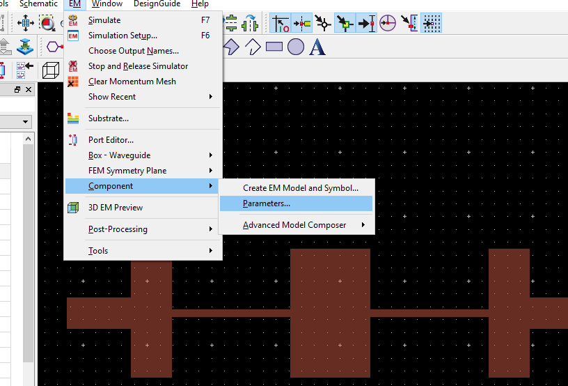
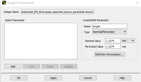
The design parameters dialog is displayed. We define the parameter name “length” (which is the size in x direction) and enter the nominal size that we have measured before. For convenience, we will define a modified (“pertubed”) length that is exactly 0.1mm larger, so we enter that value also.
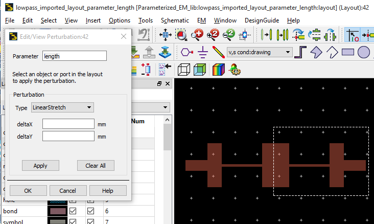
Next, we click the “Edit/View Pertubation” button and start to modify the layout so that it represents nominal value + 0.1mm = 1.3374mm length of the middle section. This is done by moving the right edge of that polygon, and everything that is connected to it, by 0.1mm to the right. To do this, we first make the selection with the left mouse button pressed down …
… define the stretch operating (deltaX = 0.1 mm, deltaY = 0mm), click apply and then OK. That’s all we need to do for the length parameter.
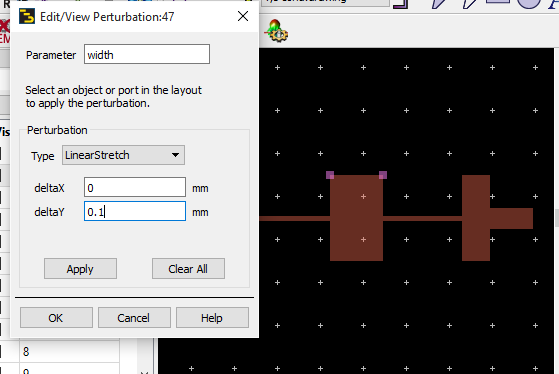
For the width, we want to stretch symmetrically up and down. For the nominal value we have 2mm, for the pertubed value we use 2.2mm. This is created by first moving only the upper edge 0.1mm (up), click Apply …
… then select only the lower edge, move that lower edge by -0.1mm (down) …
… then click Apply, then click OK.
The width and length parameters are defined and we can close the Design Parameters dialog. To check that everything works as expected, it is a good idea to place the new scalable cell in a layout window and check that it does scale as expected!
Now that we have added parameters and the layout is scalable, the remaining steps to create an emSetup/emModel/symbol are the same as described above.
[divider]
If the layout gets really complex, you might also consider custom artwork created by AEL code. This is discussed in another appnote: Miniaturized Bandpass Filter (AEL layout example)
[divider]

