
When I published the appnote on filler and ground effect for a 60GHz balun, there were a lot of comments and questions related to the ground cutout effect. It seems that many designers didn’t realize the possible loss in performance from a ground cutout that is too small. That’s enough reason to adress the issue and a possible solution again in more detail.
ADS Momentum with a dense mesh is used for this study, with a lot of experience and trust in results, based on many simulated vs. measured inductor testcases in SG13S technology.
Inductor Geometry
In this appnote, we use a two turn, 500pH octagon inductor for 28GHz in IHP SG13S technology. First, the geometry with best performance for 28GHz operation is calculated using Inductor Toolkit for ADS. The inductor is then placed over a Metal1 ground, with scalable size for the ground cutout.
Inductor geometry parameters: stacked Metal on TopMetal1 + TopMetal2, two turns, width = 7 µm, spacing = 2 µm, outer diameter = 105 µm
Regular cutout
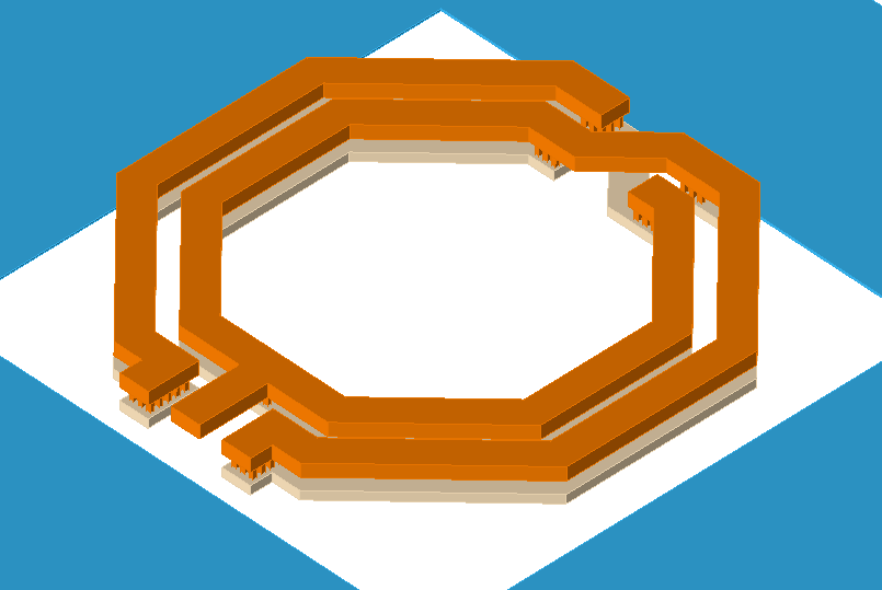
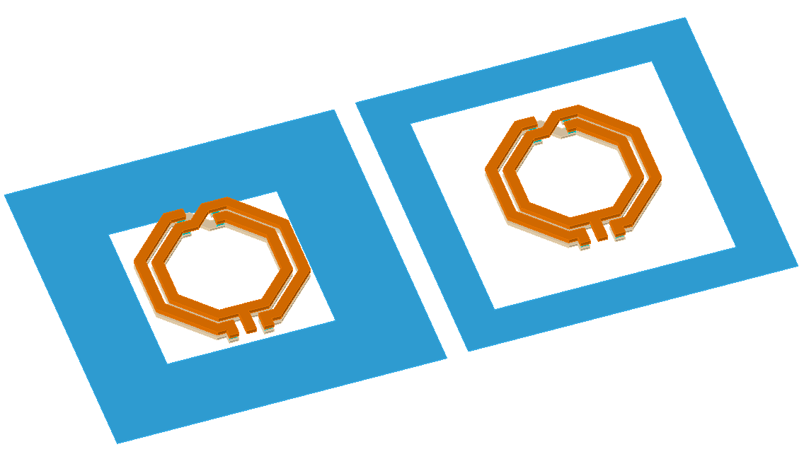
We start with a simple square cutout in Metal1 ground underneath the inductor. Distance of the cutout to the outer boundary of the inductor trace is varied from 5µm (less than one trace width) to 30µm. These two extremes are shown below.
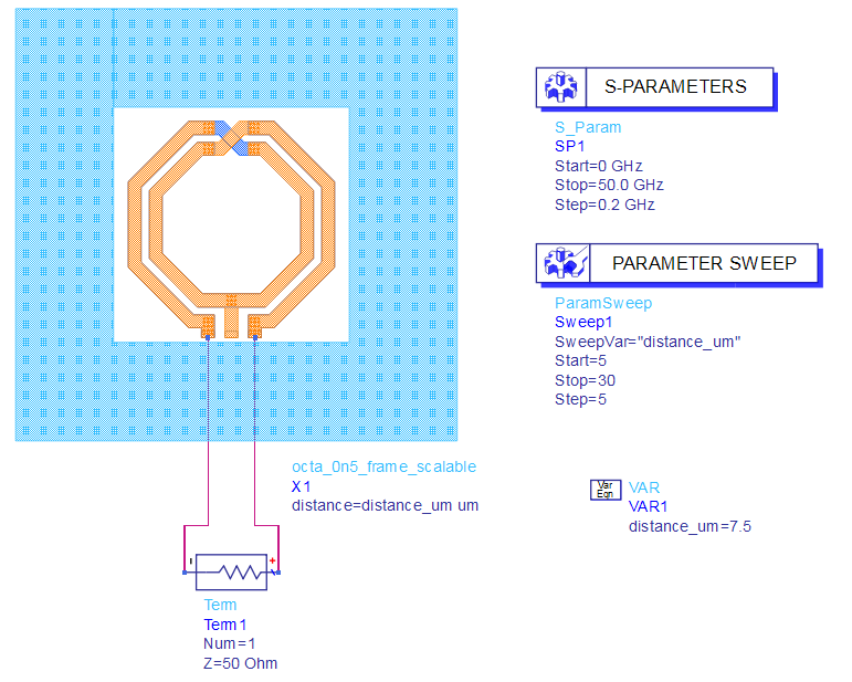
Cutout size is parameterized for EM simulation as described here, and a parameter sweep from 5 µm to 30 µm is done. The inductor is operated in differential mode, with one differential port between the two terminals.
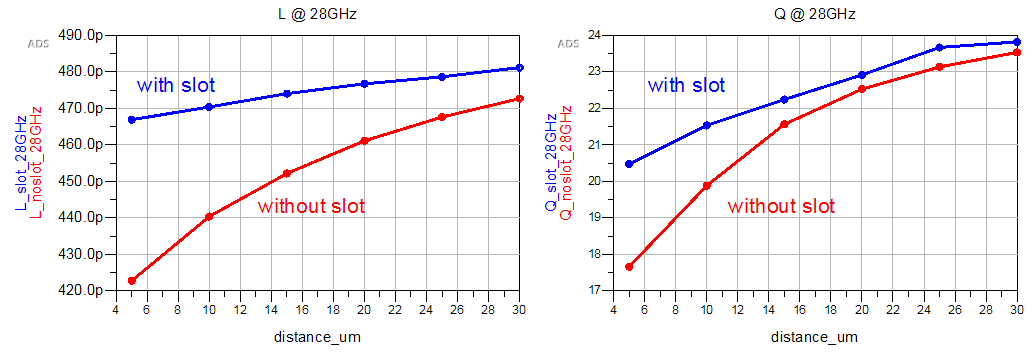
The resulting data is evaluated for L and Q factor. It is found that both parameters are sensitive to the size of the Metal1 cutout. In the plot below, the top curves show frequency response at different cutout distance. The bottom curves show results at 28GHz as a function of cutout distance.
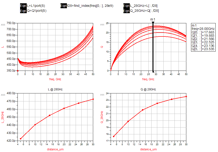
The effect of 5 µm cutout spacing vs. 30 µm is impressive in this example: 10% reduction in L value and 25% reduction in Q factor. This is very relevant for use in oscillator tank circuits.
What is the physical effect?
To understand the physical effect causing the extra loss, current density on different metal layers is plotted. At small distance between the inductor and the ground frame, there is significant current induced on the ground frame that acts like a shorted secondary turn.
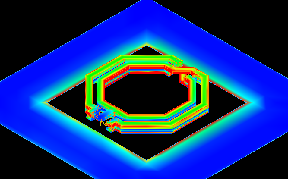
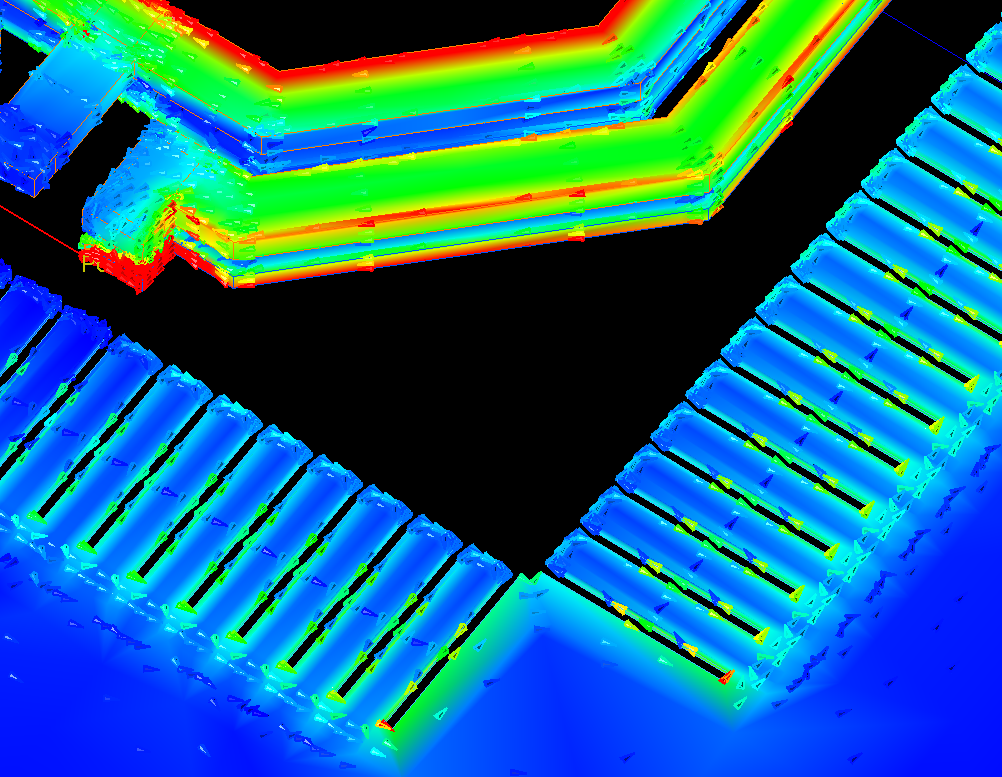
To see current orientation, arrow view is enabled in the field viewer. The detail view below shows induced current (eddy current) with direction opposite to the inductor current, causing a drop in inductance.
![]()
Prevent eddy current by adding slots
Now that we understand the physical effect that causes the reduction in performance, we can apply countermeasures. If a larger cutout is not possible or not desirable, and having a U-shaped open ground frame is not an option either, another solution might be to use multiple small slots in the ground plane to block induced current. The idea is simple: create a much larger effective path length for eddy currents. Slots must be perpendicular to the “natural” flow of eddy current seen above.

This layout with slots is parameterized and swept over the same cutout distance range from 5 µm to 30 µm. Slot length is fixed at 20µm in this testcase.
Current density at 28 GHz shows the extra path length for Metal1 eddy currents caused by the slots.
Simulation results confirm that L and Q are indeed less sensitive to ground cutout spacing when adding slots. There is still an influence, but especially at very small distances there is less loss in performance, compared to the simple square cutout.
Summary
For this 500pH octagon inductor designed for 28 GHz, we see a performance loss of 25% in Q factor and 10% reduction in L when adding a tightly spaced ground frame below. This is caused by eddy currents in the closed ground frame.
One possible workaround, besides making the cutout very large or having an open U-shaped ground frame that prevents circular current, is to add many small slots around the inductor. It was shown that this can reduce the ground frame influence, especially for very small spacings between inductor and ground frame.
In any case, when designing any RFIC inductor, you should pay attention to possible loss in performance from eddy current in closed metal structures underneath and around the inductor!
In an earlier appnote, it was shown that this eddy current issue applies even to small dummy metal fill.