
If you use Momentum and don’t know what the emModel view is, this appnote is for you. It will help you to use Momentum results more efficiently in circuit simulations.
Overview
When we run Momentum EM simulation, results are stored in a dataset. The traditional way to use that data was to place an n-port element in schematic and point it to the dataset. However, there are some drawbacks with that approach, and there is a much nicer, more efficient workflow available in ADS: using the emModel view.
The emModel view stores and manages EM simulation results. This approach is more powerful than the n-port (dataset) approach because an emModel can also handle parameter sweeps, interpolation and can start Momentum if EM data is not yet available.
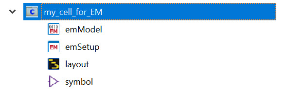
Views for our EM-simulated cell: emSetup, emModel and symbol
In addition to the layout view, we want to have these cells views for cells simulated with Momentum:
- emSetup view, to define EM simulation settings
- emModel view, to store and manage EM simulation results
- symbol view, for placing and connecting our cell in other schematics
Usually, we do not want our cell to have a schematic view. Testbenches for using our EM results must always be created in another cell.
Create the views
To create an emSetup view, use the EM Setup icon from the toolbar, or EM > Simulation Settings from the menu. When you have completed your settings for EM simulation, change to the Model tab. Enable settings to create and update the model, then press “Auto-create Now”.
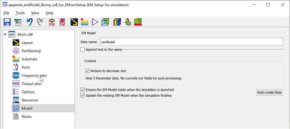
This button creates the emModel view. It has no data yet, but an emModel is able to launch a Momentum simulation “on the fly” when that data is needed. Or you can manually start Momentum simulation now, to create that data.
Finally, we need the symbol view, which visually represents the cell in schematic and defines connections. From the emSetup toolbar, you can start symbol creation using the white icon that looks like a logic gate or using Tools > Open Symbol Editor.
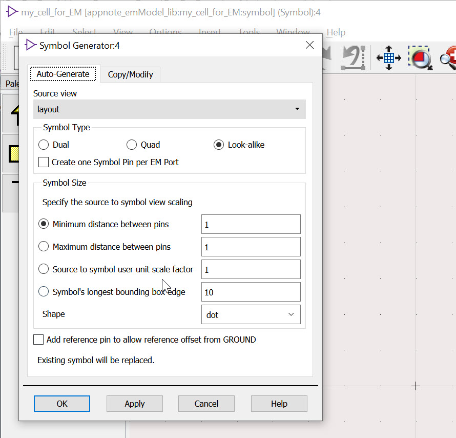
By default, ADS will create a layout look-alike symbol based on present layer visibility and with size scaled so that we have “normal” distance between all ports/pins. Sometimes, it can be useful to use a fixed scaling instead, if the automatic size of the symbol is too large.
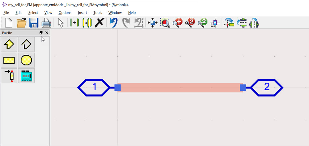
Save the symbol and we are ready to use that cell in a schematic testbench.
The testbench
Let me repeat: Do not create the testbench in the same cell that we have EM simulated. This is to make sure that our cell has a unique view for simulation: the data stored in emModel. If the cell has both schematic view and emModel view, simulation would by default use the schematic view and ignore the emModel results. You would then need to switch manually using “Choose view for simulation”. You can easily avoid that trouble by always using a separate cell for testbenches!
To use the EM cell in schematic, place the cell’s symbol in that schematic. ADS circuit simulation will use the cell’s hierarchy settings to decide what view is used for simulation: in our case, it will use the emModel view. If that has no data yet, the Momentum simulation will be started automatically.
The emModel doesn’t know what frequency range is used in schematic. Both settings are independent, but of course we want our EM simulation to cover all frequencies required in schematic simulation. You will notice a warning in the simulation log if data extrapolation happened because emModel didn’t cover the required frequency range.
Using emModel
Be careful with changes to layout after EM simulation – ADS does not automatically remove outdated results. You would need to start another EM simulation yourself, or delete the outdated EM results from emModel.
Also be careful with changes to emSetup after creating the emModel: the emModel creates a “snapshot” of the emSetup settings, and does not update automatically when emSetup is changed by the user. If you want to update the emModel settings from emSetup, use the update button on the emSetup Models tab!
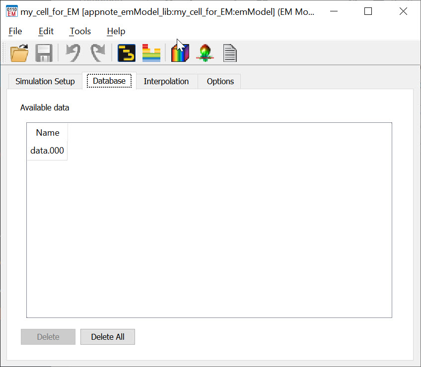
To see what EM results are stored in the emModel, and what settings are used, you can double click on the emModel. Note the “Edit…” button at the bottom of the dialog, which brings up a detailed dialog with all related EM simulation settings used for this emModel.

Here for out “static” cell that has no cell parameters, there is only one EM result stored. For a parameterized cell, we would see a list of parameter combinations that have already been simulated.
Parameter sweep
This is where the emModel workflow becomes really important and powerful: EM simulation of a parameterized layout across different parameter values (one or more parameters). In this case, emModel will maintain and organize what EM results already exist, and only start another EM simulation when needed. Using the “Interpolation” tab, we can even define what (small) variations are interpolated from existing EM data, and what difference in parameter values will trigger another EM simulation. Easy to use and very powerful!
That ends our appnote on the use of emModel. For more information and an example on parameterized EM simulation with Momentum, have a look here: Using layout parameters in Momentum EM simulations