
TexEDA layout editor LayED now includes an export function to create 3D EM Models for Empire XPU.
The interface uses an Empire model template (*.gym) with the corresponding layer mapping and then adds your layout objects drawn in TexEDA LayED. Simulation ports can be defined in LayED as planar or vertical ports (via ports). Simulation settings are defined by the model template.
Configuration
Required LayED version is 7.0.5.653 or later
To enable the EMPIRE menu item, environment variable ESY_EMPIRE must be defined and point to the Empire XPU installation directory. For example, if Empire is installed in C:\EMPIRE_XPU_8.04, the ESY_EMPIRE variable must be C:\EMPIRE_XPU_8.04
Technology template and layer mapping
Technology information is provided by the Empire template model. This is an “almost empty” Empire model in *.gym file format, with all required layer and material definitions. It also provides parameterized objects for substrate, oxide, passivation etc, as described here for the GDSII workflow.
Users of IHP technology will find updated Empire packages on the IHP PDK server.
In addition, a layer mapping file is required. To map TexEDA layer numbers to Empire layer names, the syntax is simple:
- to export all layer objects regardless of purpose: layernumber, layername
- to export on specific layer:purpose combination: layernumber:purpose, layername
Below is an example for IHP SG13 mapping, where only purpose drawing (purpose 0) is exported to the EM model:

It is possible to export different layers or layer:purpose combinations to the same Empire layer name, just specify multiple lines with all the mappings.
It is not possible to map the exact same LayED source layer:purpose to multiple Empire layers. If multiple mappings exist for the exact same layer:purpose, the last mapping in the file will take effect.
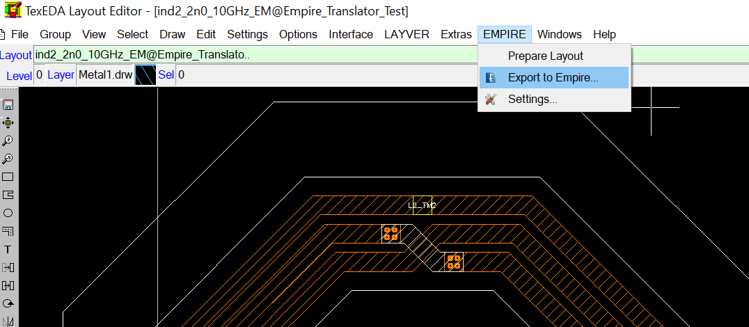
Using the Empire menu in LayED
The first step in creating an Empire simulation model is to create a “snapshot” of the layout cell, using menu item “EMPIRE > Prepare Layout”. This creates a new “flattened” layout with “_EM” appended to the name. This EM layout is opened in LayED automatically, instead of the original layout, and modifications can be done if necessary.
The bounding box of drawing objects is calculated automatically on layer 4098 EMbndry, and xmin/xmax/ymin/ymax of the simulation template are set accordingly. This sets the size of dielectric layer objects (substrate,oxide) that are included in the simulation template.
Use “EMPIRE > Settings” to configure the template and layer mapping files. These settings will be remembered during the LayED session, and used for model export.
Finally, use “EMPIRE > Export to Empire…” to create the model. The dialog will show what EM simulation ports are configured in the layout, these are then converted to Empire in-plane ports or perpendicular (via) ports.

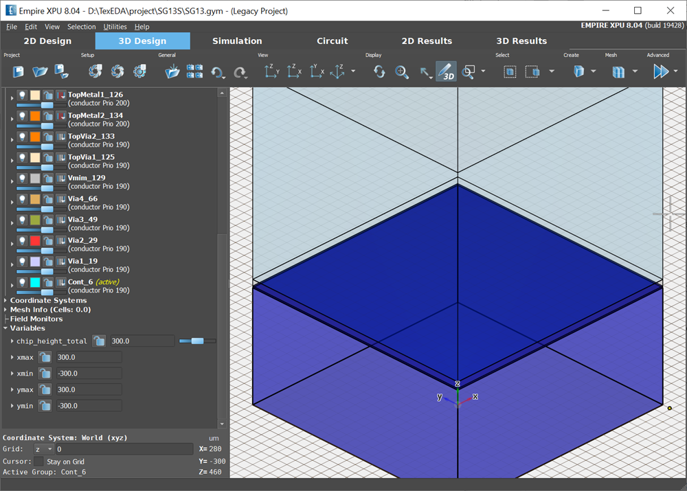
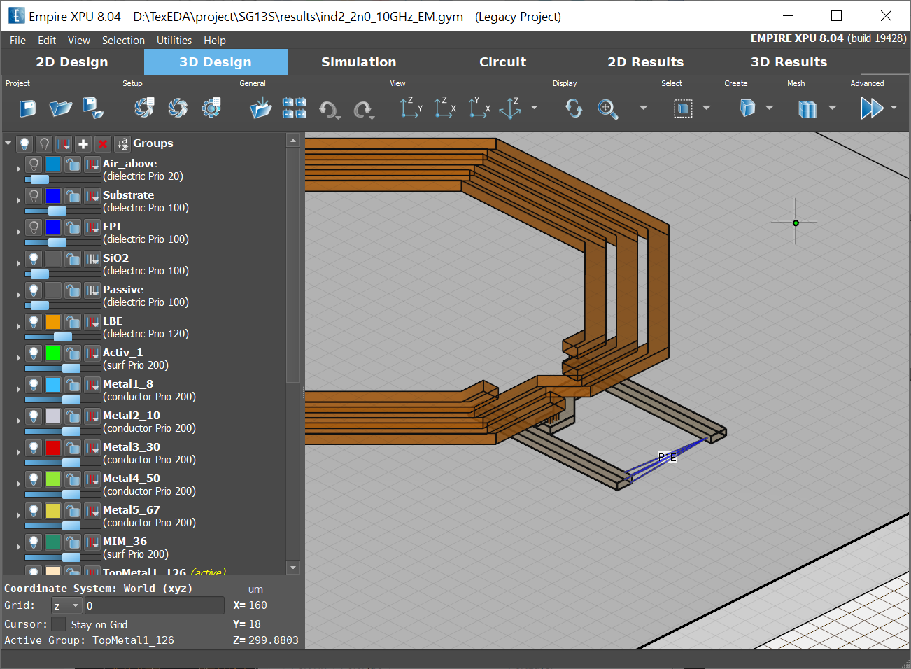
Export will create a script file containing geometry and ports, which is then automatically loaded into the simulation template. When the Empire editor comes up, you will see the combined model from technology template plus your geometries.
Defining ports for EM simulation in LayED
You can define ports for EM simulation in LayED, which are then used in the EM model. Two port types are available: horizontal ports (in-plane) and vertical ports (perpendicular).
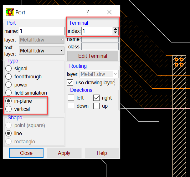
Horizontal ports on metal layers
In-plane ports are defined between two polygon edges on the same layer, by drawing a straight line (0°/90°) from one edge to the other. This line defines the center line of the port. The port is then created in the gap between both conductors.
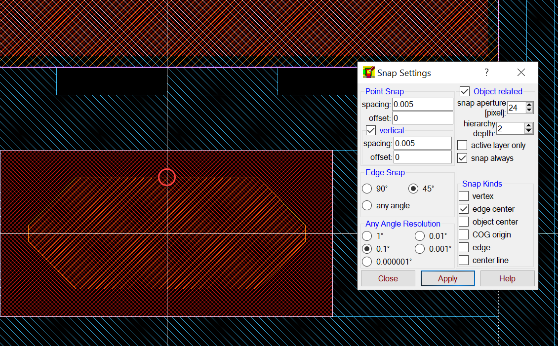
To start/end the line for the port at the center of a polygon edge, use the snap function:
Object related snap + snap always + edge center snap (but NOT center snap!)
Ports are created on the current drawing layer, so you must set the correct drawing layer in LayED before drawing the port!
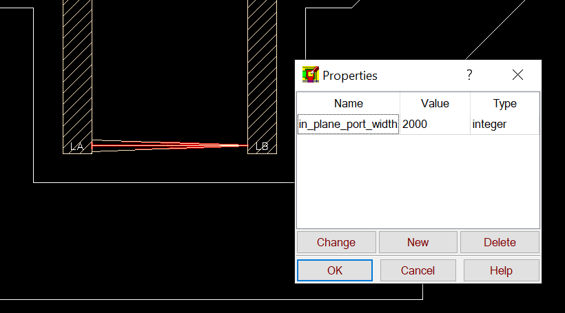
Port width is set automatically and can be changed any time, it is defined as a property of the port object. Note that units for port width are database units (e.g. 1 nm for IHP SG13) !
Vertical ports (via ports)
Ports can also be defined as vertical (via) ports, by drawing a rectangle. However, there is one important detail: in old Empire templates, via span in the technology template was defined from the bottom of the upper layer to the bottom of the lower layer. If you place a vertical port on a these via layers that pass through the bottom metal, the port will partially overlap with the low metal layer, shorting parts of the port. This gives incorrect results and/or trouble in port excitation (no convergence).

It is important that ports never overlap (fully or partially) with metal objects, they must not intrude into the lower metal!
Updated Empire templates (September 2021 or later) have via layer positions that start at the top of metal conductors, so that vertical ports on via layers work as expected.
If you are still using an old Empire templates and notice such an overlap for vertical ports, you MUST to either modify the port z-position manually in Empire editor for your model (use side view in 2D editor) or change via layer zmin value in your template, so that via layers start at the top surface of the lower metal.