Control the port size and location
Defining EM ports is among the most crucial topics in EM simulation. For accurate results, the port type and port ground reference and port calibration must be chosen with care.
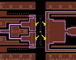
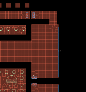
In this appnote, we will discuss port setup for connecting power amplifier transistors to the PCB matching networks. The difficulty with this application is that we can’t just place an EM port somewhere on the edge of the PCB polygon. There is one obvious reason – on the output side we need two ports at different locations on the same polygon edge – and one less obvious reason: If we place a pin on the edge of the polygon, Momentum will use that entire width of the polygon edge for the port. This is not what we want, and we would get wrong results.
Now we have multiple options to solve this, and tell Momentum more clearly where we want to place the port. If we move the pin inside the polygon, this will create a point port at the pin location, instead of an edge port along the edge with the pin. That simple point port is not appropriate here, because the transistor terminals are really wide, and the connection between the PCB and the wide transitor terminals would be mis-represented by using a small single point for that port. With a point port, all port current would need to flow to that small point in Momentum, and that is obviously much different from the real hardware with wide lines. With the point port in the EM model, we would introduce series inductance that doesn’t exist in the hardware, and this would be located at a low impedance point in the circuit where it really matters. No, we can’t use a simple point port.
One great solution are edge/area pins, which are supported in Momentum since ADS 2011. This gives us control over the port edge length (for edge ports) or port area (for internal ports inside a polyon).
Why do we need all this?
For accurate results from EM, the current in the model needs to flow in the physically correct way, similar to the hardware. With edge/area pins, we can help Momentum to create the physically correct current flow in complex port configurations.
Edge port with user defined location and size
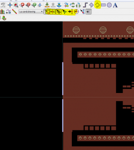
For connecting the two drain terminals to the output metal, we can use an edge port with user defined location and size. These are created by drawing a line at the desired port location, and then attaching the pin to the line with the Edit > Edge/Area pin … command. To draw the line, use the polyline tool. Snap modes can be useful to draw the line exactly along the edge, at the intersection between the PCB and the transistor lead boundary.
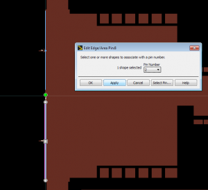
Next, add the pins that we want to use for the Momentum ports. Finally, select (one at each time) the line that you have drawn and assign it to the pin with the Edit > Edge/Area pin … command. Note that the pin must be located on the line, but the exact location does not matter.
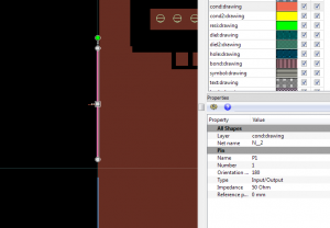
Edge/area pins that you have created this way are easily identified by the blue color. If you click on an edge/area pin, you can see the properties and assigned pin number in the Properties window.
Area pins with user defined location and size
In the text above, you might have noticed the description “edge/area pin”. Just like edge pins with user defined location and size, we can also control area pins. These are used to control the area of an internal port, instead of just making it “very small” and let Momentum choose some size that depends on the mesh. If we manually control the area pin size, Momentum will equally distribute the injected current across that area.
Creating an area pin is very similar to creating an edge pin, but we need to draw a rectangle or polygon instead of the line. The pin must be on the polygon, but the exact location on the polygon does not matter.
Edge/area pins in FEM
Edge/area pins described above are available for the Momentum solver. FEM in ADS 2014 does support edge pins when the edge is a line segment. Area pins are not supported by FEM. A point pin, at the location of the pin symbol, will be used instead.
Current flow for different pin types
For a better understanding of the pin/port options, the current flow with different configurations is visualized below. The testcase is a small conductor with a via to ground on one side, with different port configurations.
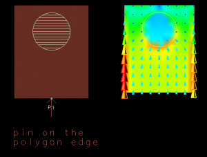
Pin placed on the edge of a polygon
The screenshot below shows the current flow for a pin/port that is placed on the edge of a polygon. The size of the polygone edge determines the port size. The port current flows into the metal along the complete edge.
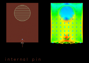
Pin placed inside the metal area
The screenshot below shows the current flow for a pin/port that is placed inside a polygon. The port size is very small, and the exact size depends on the mesh settings. The port current flows into the metal at that “point”.
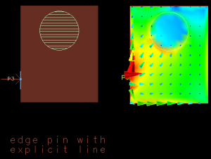
Edge/area pin attached to a drawn line (on polygon boundary)
The screenshot below shows the current flow for an edge/area pin that attached to an additional line that we have drawn on the metal layer, on the edge of an existing metal polygon. The position and length of the line determines the port size. The port current flows into the metal along that line.
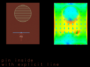
Edge/area pin attached to a drawn line (inside metal polygon)
The screenshot below shows the current flow for an edge/area pin that attached to an additional line that we have drawn on the metal layer, inside the conductor metal area. The position and length of the line determines the port size. The port current flows into the metal along that line.
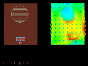
Edge/area pin attached to a drawn rectangle
The screenshot below shows the current flow for an edge/area pin that attached to an additional rectangle that we have drawn on the metal layer. The position and size of the rectangle determines the port size. The port current flows into the metal at that area port, distributed over the area of the rectangle.
Recommended reading
ADS online help, chapters
Simulation > Electromagnetic > Ports > Defining Ports in EM Simulations > Using Edge and Area Pins
and
Design Tools > Schematic Capture and Layout > Layout > Using Edge and Area Pins

