How to simulate RFIC inductors in Momentum, as 1-port or 2-port EM models?
Why do we get different results for the Q factor, and which is right?
When EM simulating on-chip inductors, it is not obvious which port configuration is “best”. Depending on the port configuration, the extracted inductor properties can be very different.
In this document, we will review the different configurations, and find out what is most suited for parameter extraction and modelling.
EM setup: 1-port or 2-port
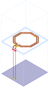
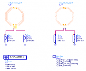
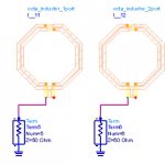
In a typical substrate for RFIC EM simulations, there is an infinite ground at the bottom of the stackup, below the silicon substrate. The distance between pins on the metal layers and that infinite ground plane is rather large, leading to EM models that look like this (center tap unconnected in this example):
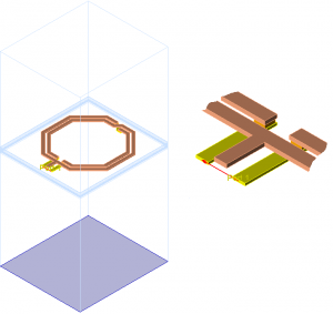
The ports have a large distance between the (+) pin on the metal layer, and the infinite ground at the bottom of the substrate. Some users might intuitively prefer to define the EM model where the combine the two pins into one port:
Both configurations are valid from an EM simulation viewpoint, but the differential 1-port configuration only provides valid results for purely differential excitation. Connected in a circuit with single ended or mixed excitation, results are not valid. Usually, the 2-port configuration is what you want for modelling, to have correct results for all possible excitations. This is discussed below.
Inductor in differential mode
Differential operation is the typical use case in oscillator tank circuits and other circuits.
We can always connect the full 2-port EM data in differential configuration at schematic level, to see how it performs with differential signal. For purely differential use in the circuit, this provides the same results as 1-port EM simulations, but it will also provide correct common mode or mixed mode data when needed.
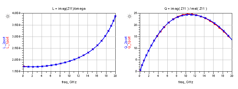
So we get identical results from 1-port and 2-port EM data when connecting them purely differentially at schematic level.
The inductance and Q factor for this differential mode (“Differential L and Q”) is what many circuit designers are interested in. Note that differential Q factor and self resonance are different from results in single ended configuration, so we need to document what data is shown, differential or single ended.
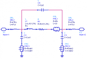
Besides getting correct results for all possible excitations (e.g. differential circuit with some residual common mode signal), another advantage of EM-simulating the full 2-port EM data is that it can be used to extract the inductor’s equivalent circuit model. This is not possible with 1-port data, because series and shunt path elements can’t be separated from 1-port data. This is only possible with the full 2-port data.
Common mode – where 1-port simulation becomes invalid
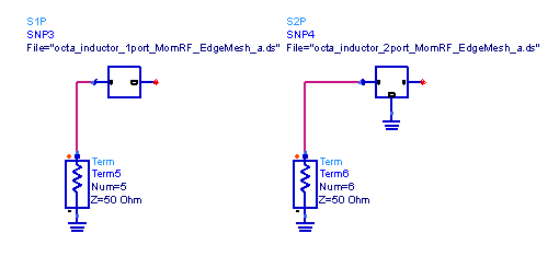
If we use the ADS layout-lookalike symbol, both 1-port and 2-port symbol look identical. The reference pin of the 1-port simulation is available as a separate pin at schematic level, just like port 2 of the 2-port simulation. Now, it is important to understand that both EM data blocks are not equivalent, although the symbol looks the same. This can be easily demonstrated by connecting the symmetrical 1-port data in a non-symmetrical way, and compare it to 2-port EM data:
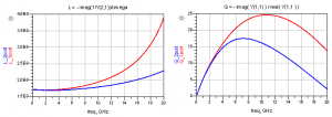
Comparing both configurations, you will find obvious differences in S11 (S33) and in the single ended inductance and single ended Q factor:
There is nothing wrong with ADS or Momentum. These differences are caused by the user, who has connected the ports differently in EM and circuit level simulation.
Why are these results different?
In the 2-port EM results, we have valid data for all possible combinations of pin/port1 and pin/port2 to ground. This includes differential connection between the pins, as well as “single ended” connection from each pin to ground.
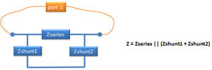
In the 1-port EM results, we have less data. S-Parameters for 1-port correspond to an impedance between the (+) and (-) node. For the inductor, the 1-port simulation provides an effective value that is the parallel connection of series path and cascaded shunt paths. This results in one impedance, which is valid for this exact port configuration.
Once reduced to 1-port data = one impedance value, we can never again separate shunt path and series path from that data.
If we look at the “black-box” symbol for EM results, the difference between 1-port and 2-port data is more obvious than with the layout-look-alike:
Even if we re-wire the symbol for the 1-port data, it remains a single impedance value. For the inductor, this means that a 1-port EM block re-wired into series connection has only that series path (impedance as calculated for the EM port configuration), but no shunt path to ground. That separate data just doesn’t exist, and can’t be extracted from 1-port EM data.
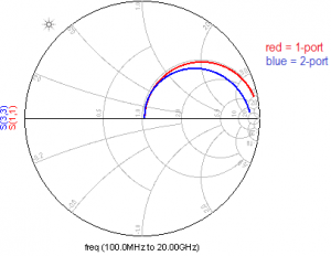
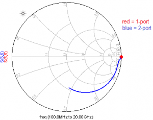
Does it matter? Yes! This can be shown by simulating the inductor with one side floating. This breaks the series path, but proper real-world results should still show the effect of shunt path current flowing to the substrate.
Indeed, this shunt path is seen in the 2-port simulation results (blue curve). However, for the 1-port EM data block, we see an ideal open circuit. No surprise, because there is no separate shunt path data available.
The 2-port EM does have valid shunt path data flowing to the grounded reference node. The 1-port EM data provides just an effective impedance between the (+) and (-) pins, and that is floating on one side. The re-wired 1-port is a pure series element, with no shunt path, so it provides an open circuit (red circle) when connected this way.
We can conclude that the 2-port data is more flexible, because it works in all series and shunt configurations. The 1-port data with differential port configuration is only valid for that differential configuration. If the separate pins in the schematic symbol are “abused” to wire other configurations, results will be wrong.
Conversion from 2-port data to differential 1-port data
For the ADS data display, it is convenient to calculate the differential 1-port data from 2-port data by an equation, without having to run an additional schematic simulation. The equations for that 2-port data to differential 1-port data conversion are:
Z = stoz(S)
omega = indep(S) * 2 * pi
Zdiff = Z(1,1) – Z(1,2) – Z(2,1) + Z(2,2)
Qdiff = imag(Zdiff) / real(Zdiff)
Ldiff = imag(Zdiff) / omega

