
In this application note, we compare two on-chip transformer layout styles with 2:1 turn ratio. Target frequency is 60 GHz, nominal impedances are 200 Ohm primary and 50 Ohm secondary. Technology used for this study is IHP SG13S BiCMOS with 3 µm and 2 µm Al top layers, separated by 2.8 µm oxide.
Muehlhaus RFIC Inductor Toolkit was used to find the best geometry for 60 GHz operation within a predefined parameter space, starting from a nominal primary inductance of 1nH.
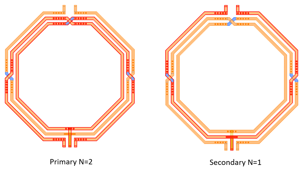
Interleaved geometry
The first transformer shape is an interleaved configuration, which is scalable for different turn ratio. Here, we use 2:1 turns. Outside the crossovers, metal layers are stacked (connected in parallel) for lowest resistance.
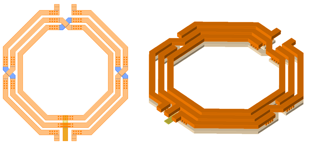
Overlay geometry
For the overlay transformer, we use a geometry style provided by Simon Küppers of Fraunhofer FHR. This has a fixed 2:1 ratio, and is tweaked for best possible symmetry. The “single turn” is implemented by two co-axial turns connected in parallel, to reduce series resistance.
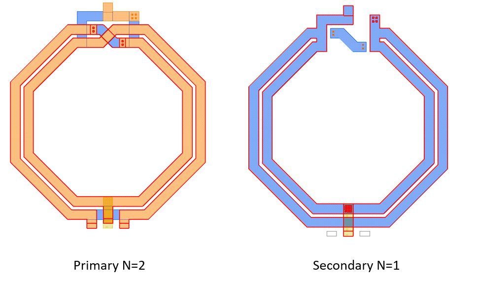
For some technologies and design frequencies, this layout style provides a much lower insertion loss than the interleaved geometry. Simon allowed us to include this layout style in Inductor Toolkit – many thanks, Simon!
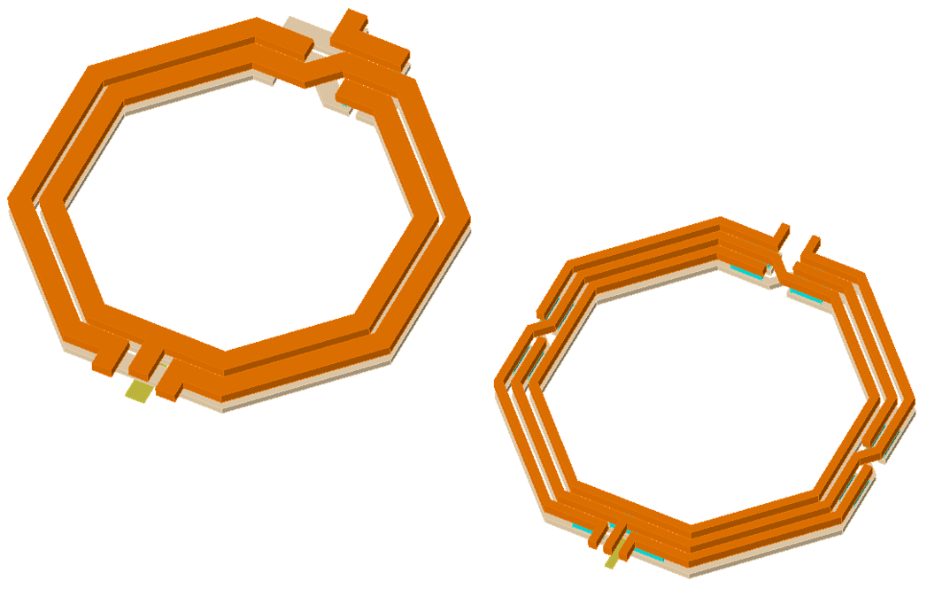
Size comparison
The overlay transformer uses vertically overlayed turns on adjacent layers, so the number of turns is determined by the larger of the turn numbers. The interleaved transformer uses horizontally interleaved turns, so in our testcase we have 2+1 turns total.
Despite having less turns per layer, the best overlay transformer (smallest insertion loss) results in a larger layout than the best interleaved transformer. This is because the interleaved transformer shows best results at small spacing and small line width for our testcase, whereas the overlay transformer performs best with a medium line width value (5.5µm width at 2.1µm spacing).
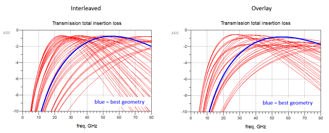
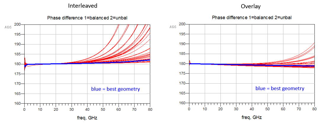
Using these best parameter sets, both transformers give rather similar performance, with an insertion loss of around -0.8 dB. Below are results for interleaved transformer (left) and overlay transformer (right). The blue curves show the parameter combinations with the smallest 60 GHz insertion loss in a 200 Ohm / 50 Ohm configuration.
Performance at different parameter sets can be compared using the “top list”, to learn about good/bad parameter value ranges, and sensitivity to different parameters. This is the top list for the overlay transformer, with 0.7nH norminal inductance for the primary turn:
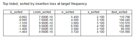
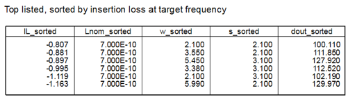
where IL is S21 in dB, Lnom is the nominal primary inductance, w and s are width and spacing in µm and dout is the outer diameter in µm.
Top list for the interleaved transformer, with 0.7nH norminal inductance for the primary. This shape shows less variation in performance for the top rated parameter combinations:
Amplitude imbalance is less than 0.1dB for both balun styles.
Further refinement
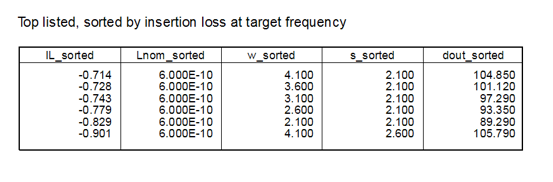
After this initial sweep across the geometry space, another detail analysis was performed for the interleaved layout. With the previous transformer candidates at 0.7nH primary inductance, frequency of minimum insertion loss was slightly below 60GHz, so the target inductance was now changed to 0.6nH. Geometry sweep range was narrowed to values around the previous optimum.
This second iteration results in the final layout, with an insertion loss of -0.71 dB in a 200 Ohm to 50 Ohm configuration. S11 is around -15dB.

The optimum width of the interleaved transformer has increased a bit. From the top list, we can see the small sensitvity to the trace with:
If we use that width and accept the increase in size, the final 60 GHz interleaved transformer/balun has an outer diameter of 105µm. This is 5µm smaller than the overlay transformer, and gives 0.15 dB better insertion loss for this testcase. Usable bandwidth of both configurations is about the same.
Summary
For this technology and target frequency, a 2:1 balun implemented in overlay and interleaved transformer style has about the same performance, with a small advantage for the interleaved style. In both cases, best performance was obtained with minimum design rule spacing, for maximum coupling between the coils.
In the next application note, we will check transformer performance when dummy metal fill and ground frame metal is included in simulation. Stay tuned!