
In 2018 Rogers Corp. introduced MAGTREX™ 555, a laminate featuring a high permeability and high permittivity. One possible application is to shrink antennas by up to factor 6, with much larger bandwith than regular µr=1 substrates at the same antenna size. We will investigate that in this simulation report.
[box type=success]Quote from Rogers Corp press release: “These high impedance laminates enable antenna designers to expand the trade-space of their antenna design enabling up to a factor of six reduction in size with minimal impact on bandwidth, up to a factor of six increase in bandwidth with similar size, or a design optimum in between.”[/box]
The possible shrinking factor for antenna size is approximately sqrt(εr*μr), and Magtrex is unique by providing εr=6 µr=6. In addition to massive shrinkage, this ratio of εr and µr gives low impedance on the order of free space impedance, for increased antenna bandwith
We will compare simulated performance and bandwith of a patch antenna on Magtrex substrate with a patch antenna on “regular” substrate. To achieve the same small patch size, the regular substrate permittivity is increased to εr=30 at μr=1.
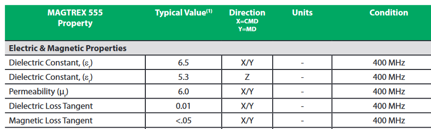
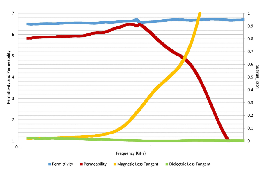
The main limitation of Magtrex laminate is frequency range: it is designed for frequency range up to 500 MHz only (no typo!), and magnetic loss factor quickly increasing above 500 MHz. A detailed graph on loss vs. frequency can be found in the data sheet:
To investigate performance and the claimed improvement in bandwith, we will simulate a microstrip patch antenna at 433 MHz ISM band.
433 MHz patch antenna size: 66mm x 80mm
Due to high permittivity and permeability of the Magtrex laminate, patch size for 433 MHz is only 66mm x 80mm. The data sheet specifies slightly anisotripic permittivity, which is properly modelled in the Empire XPU simulation model. Substrate thickness is 6.6mm. Port excitation is done using a via port (probe feed).
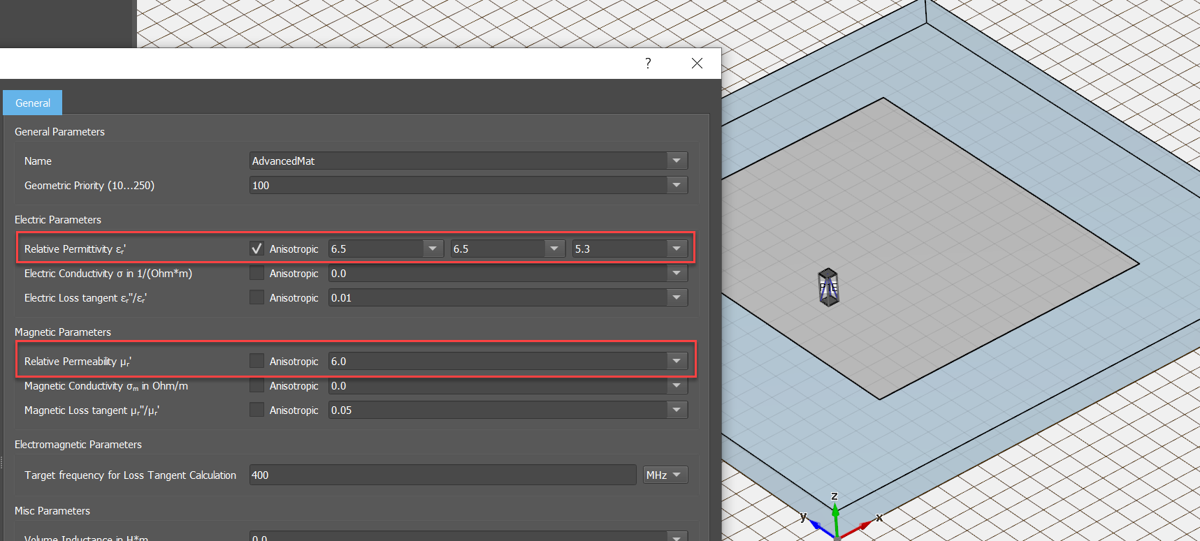
(click to enlarge)
On “regular” substrate, εr=30 was selected because that is what Rogers specifies as the equivalent material for similar shrinkage. From simulation we get a patch size of 60mm x 80mm for 433 MHz center frequency, that is indeed quite close to the Magtrex patch size. Loss tangent is selected as 0.002 for this comparison, which means much lower loss than Magtrex.
Bandwith for the Magtrex antenna is 19.1 MHz @ -10dB (4.4%), compared to 1.4 MHz (0.3%) for the high permittivity “normal” ceramic.

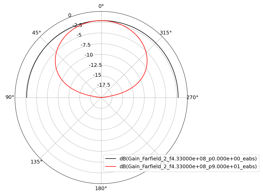
That robust bandwidth at tiny size is a major advantage for the Magtrex laminate version, but it comes at a price: radiation efficiency is only 20% due to substrate losses, gain is -2dBi. At 433 MHz we are already at the upper end of the usable frequency range for this material.
Side note: The increased bandwidth is not simply a result of substrate loss. If we add more substrate loss to the regular substrate to achieve the same low 20% radiation efficiency, a large difference in bandwidth remains. Bandwidth on lossy regular substrate is 0.7% @ -10dB, compared to 4.4% for the Magtrex patch antenna. It is really the εr/μr ratio that makes a difference.
Summary
Simulations show that this laminate delivers what Rogers promised: it provides shrinkage and low impedance (small εr/µr ratio) for wide bandwidth. Useful frequency range is limited due to loss, but in the lower UHF range this material enables antennas that are otherwise difficult to implement with similar bandwidth.
As outlined in the data sheet, the material might also be used as a loading material in sandwich configurations, if less shrinkage is required.
Download the Empire XPU simulation model (*.zip, 13kB)