
During these strange corona home office days, I wanted to prepare some moonbounce experiments on 432MHz.
While testing, I experienced excessive noise from all sorts of electronic devices, which was not sufficiently surpressed by the antenna pattern even when pointing up in the sky. Looking for a possible solution, I came across the “low noise” yagi designs by DG7YBN that are optimized for low sidelobes, and decided to study the GTV 70-14m design using Empire 3D FDTD simulation.
The antenna design by Hartmut Klüver (DG7YBN) is described here in detail:
http://dg7ybn.de/432MHz/GTV70_14.htm
Hartmut optimized this 14 element yagi antenna using EZNEC, which is a perfect fit for such “wire” antennas with 1-dimensional elements. However, the unique “blade” dipole that he invented is actually a flat and wide object that can’t be represented as a wire. If we extend the model further using coax feed, we have a 3D structure and in this application report, I will use Empire XPU to model such 3D details.
Bent round tube or flat blade?
Mislead by the simple geometry, I tried to include many real world elements like plastic element holders etc. at once, in my very first model. For the blade dipole, I used dimensions described here. To my surprise, results where quite different from Hartmut’s simulation. After discussion with Hartmut, I stripped down my Empire model and removed boom and plastic support, to have a simple base model that mimics his EZNEC design.
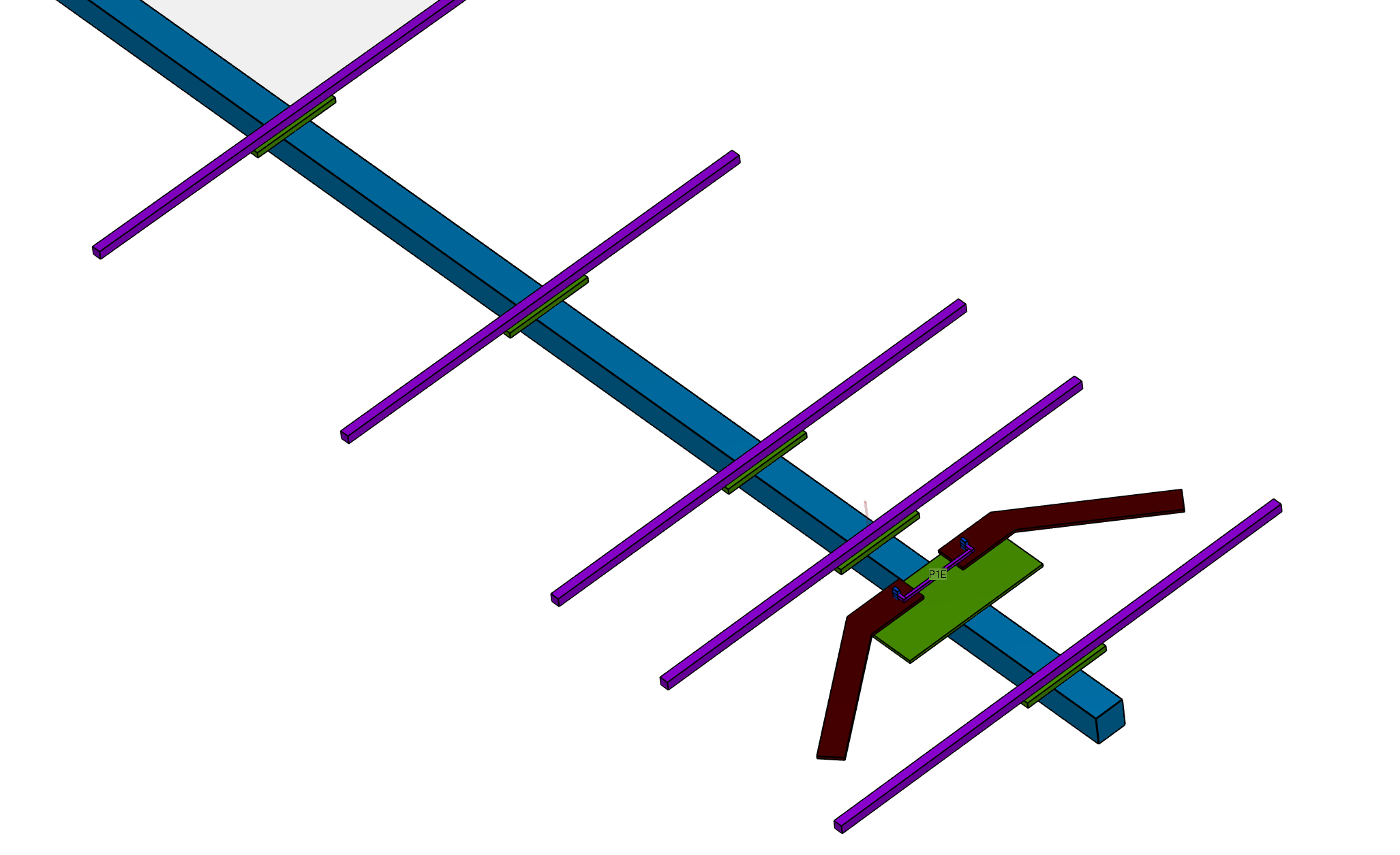
It turned out that the major difference was caused by the blade dipole, which was originally designed for the 19 element yagi. Blade dimensions were very different from the bent 10mm tube that he simulated in EZNEC for the 14 element design, and the coax-to-blade transition using wires adds some design uncertainty:
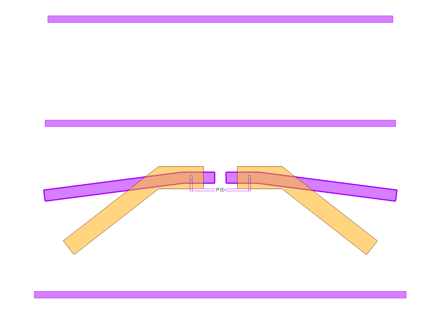
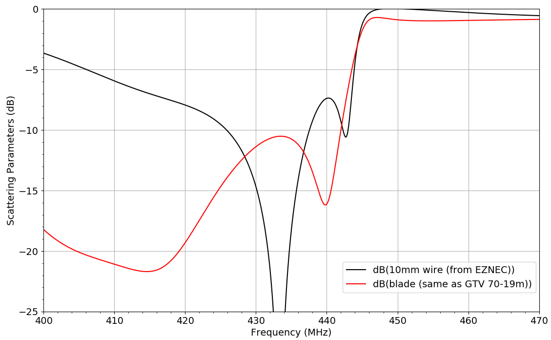
Using a 10mm tube dipole as modelled in EZNEC, I could immediately reproduce the good matching at 432MHz (red curve). When switching to the blade dipole which has a very different angle, return loss was significantly worse (black curve). Obviously blade dimensions and angle must be modified to use it with this antenna, these dependencies will be studied later in this document.
With the tube dipole instead of the (very different) blade, an antenna pattern with low sidelobes was confirmed in the azimuth pattern:
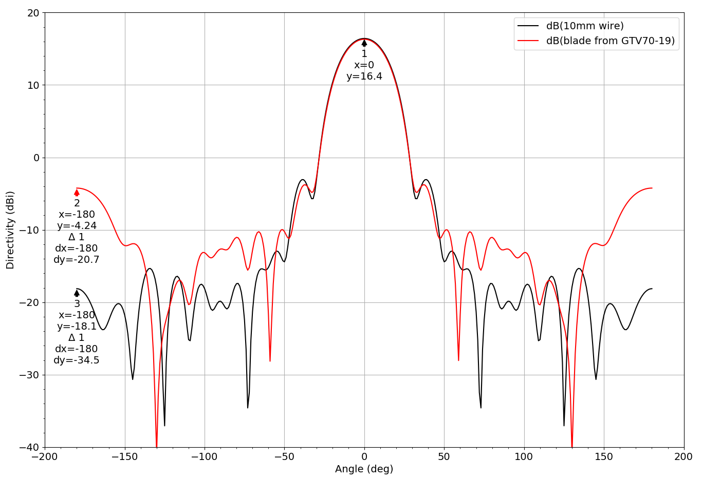
Maximum directivity of 16.4 dBi agrees with Hartmut’s EZNEC results, and 34dB F/B ratio agrees for the bent tube dipole (red curve). The blade dipole thta isn’t optimized to this antenna (black curve) performs worse in both return loss and pattern: only 21dB F/B ratio, so dimensions and angle need to be tweaked.
The basics: bent dipole geometry tweaking
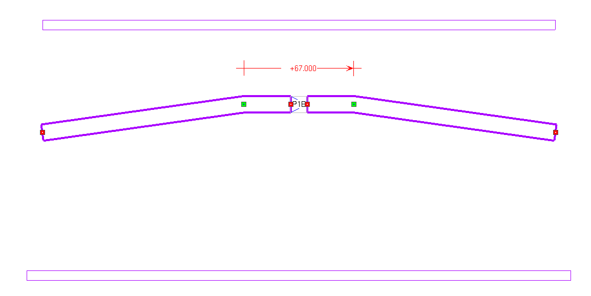
To better understand the bent dipole, we reduce model complexity and study a basic design similar to EZNEC simulations: We use the 10mm tube model and vary two parameters, bending angle and dipole length. The center section is fixed at 67mm length, and from there we can change angle and length of both arms. The picture below shows an angle of 8°
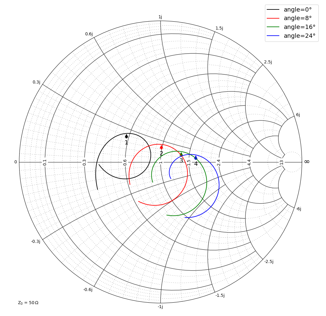
Hartmut describes that antenna input impedance is tuned by that angle, and simulation results below show that effect. Frequency range is 420-440 MHz, marker is at 432MHz on all curves. Antenna input impedance real part increases as we increase the angle. We find real part of to 50 Ohm at around 8° angle.
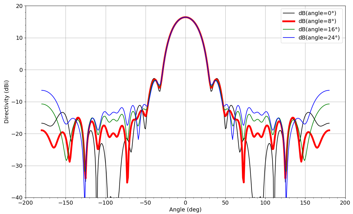
F/B ratio and sidelobe surpression is also best at 8° angle:
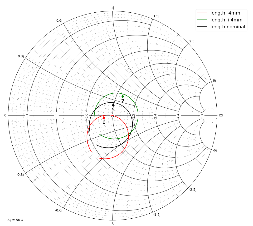
Next we tune the dipole length, at a fixed angle of 8°. It can be seen that more length tunes to inductive +jX reactance, less length tunes to capacitive -jX reactance. That is actually very nice: both effects are almost orthogonal, which enables tuning of the input impedance as desired. For antenna pattern, +/- 4mm length tuning has no relevant effect.
Boom correction
In his design documentation, Hartmut provides a boom correction value sbc that is added on top of all element lengths, to compensate for different boom dimensions, different element holders etc. but also compensate numerical artefacts from simulation.
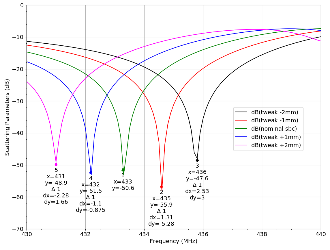
So far, we have used his “base sbc” for the no-boom case which is 1.65mm using EZNEC. It is uncertain if that value is applicable to our Empire FDTD simulations, because it also includes some EZNEC segmentation effects. To check that, we use the bent tube design with nominal sbc=1.65mm (valid for EZNEC) and vary that by +/- 2mm. All element lengths including the dipole are tuned by that diffence.
The difference in sbc to Hartmut’s EZNEC simulations seems to be 1mm or less.
1mm change corresponds to ~1 MHz frequency shift in resonance.
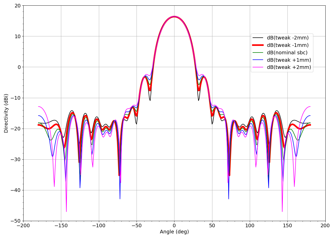
For the antenna pattern, we find that especially the backlobe at 180° is sensitive to these small sbc changes:
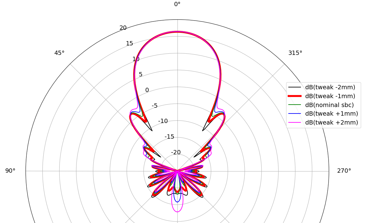
The same patterns in polar plot:
Dipole feed: Simulation vs. Coax
Going from simulation to hardware, we have two major differences in the feed: parasitics introduced in the feed and the balanced/unbalanced issue when using a coax feed.
Feed parasitics
The center-wire-feed in EZNEC and the series port used above in the bent tube model are very “ideal”. In a real transition from coax to the dipole, we have some length of wire in that connection, which means some series inductance. Looking at the parameter sweeps above, we can compensate extra series inductance by shortening the dipole. If that is just a few millimeters, it will not change the radiation pattern, according to simulation results shown above.
Unbalanced coax to balanced dipole
The coax shield is connected to local ground somewhere at the transceiver, but at the dipole we need a perfectly symmetric signal. If we just hook the coax to the dipole, we have a mixture of differential and common mode signals, which will distort the radiation pattern.
The coax itself will then be part of the radiating structure, and distort the pattern. This is discussed in part 2 of this application note: Balun.
Disclaimer: The entire antenna design is (c) DG7YBN. If there is any misunderstanding or mistake in the simulation report and documentation here, that is my mistake. Don’t hesitate to contact me if you spot mistakes or have any ideas for improving the model.