
In part 1 of this appnote, we looked at some basic properties of the DG7YBN yagi antenna design.
Next, we will have a look at the balun used to drive the dipole feed (symmetric, balanced) from a coax feed (unbalanced, shield grounded). In simulations, we often use a lumped source which has no connection to global ground, but in real hardware that coax and grounded parts of the antenna might act as a 3-conductor system with multiple modes, resulting in possible distortion of the antenna pattern.
Dipole feed: Unbalanced coax to balanced dipole
The coax shield is connected to local ground somewhere at the transceiver, and we want that to be “RF ground”. But at the dipole we need a perfectly symmetric signal, with +V/2 and -V/2 at the two terminals. If we just hook the coax to the dipole, we have a mixture of differential and common mode signals, which will distort the radiation pattern. The coax itself will then be part of the radiating structure.
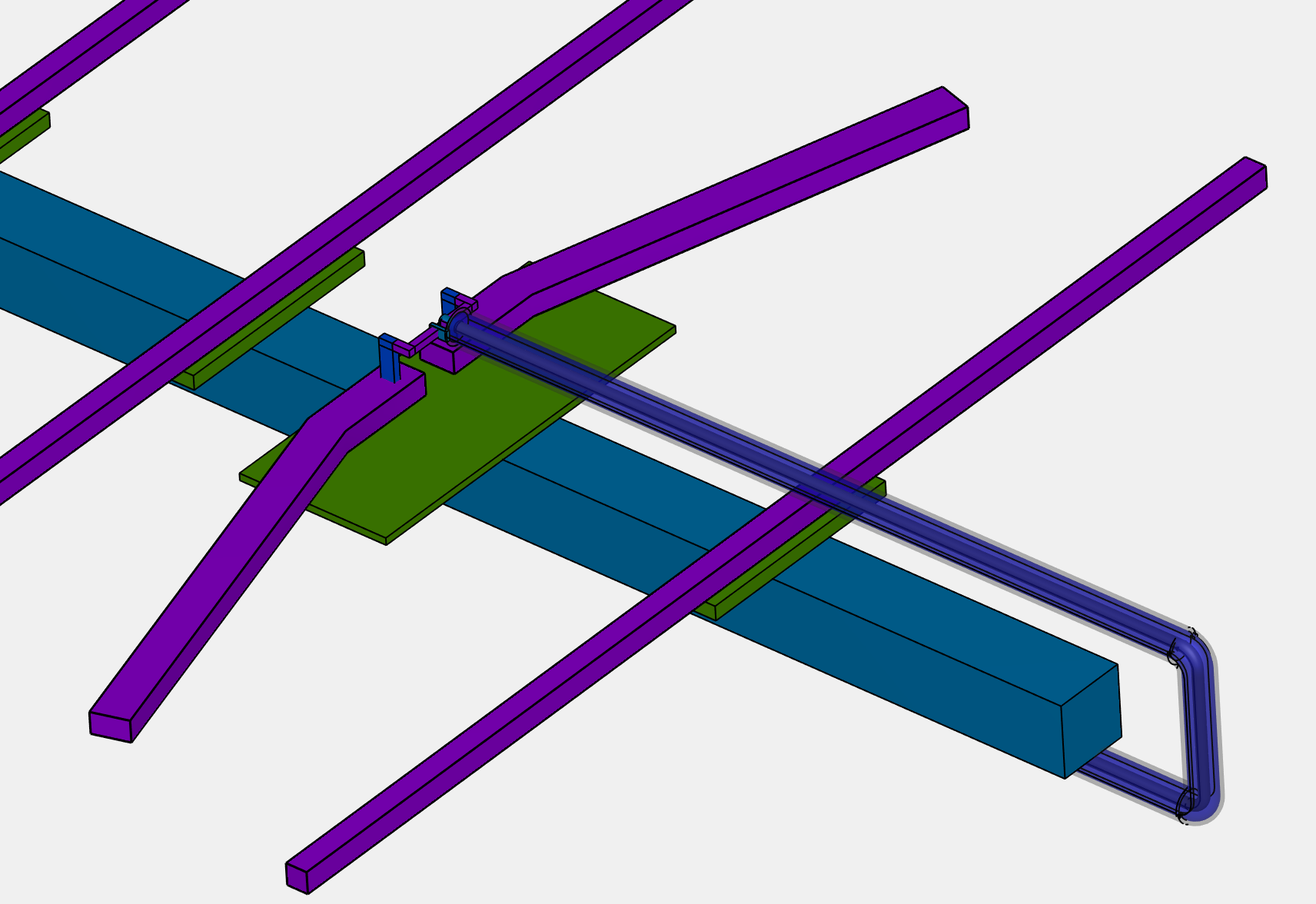
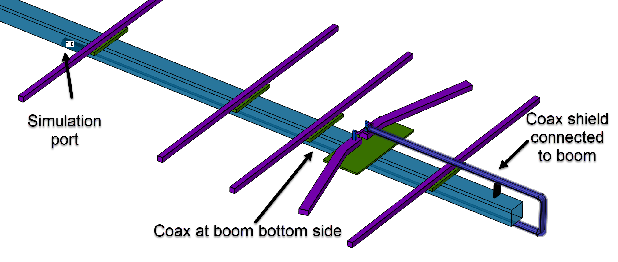
For motivation, let’s look at “bad” simulation example where the coax is connected to the dipole, with no attention to any balun. The coax cable is then placed along the bottom side of the boom.
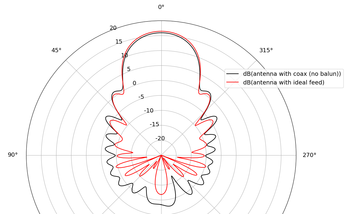
The azimuth antenna pattern simulated without the coax was nice (red curve), but adding this careless coax feed without balun (black curve) results in a distorted asymmetric pattern with much stronger sidelobes. Antenna gain is reduced by 0.5 dB, but for EME noise coming in from the side lobes might be the bigger issue.

In the elevation pattern, we see the same thing: much stronger side lobes of the no-balun coax model compared to the “ideal feed” model:
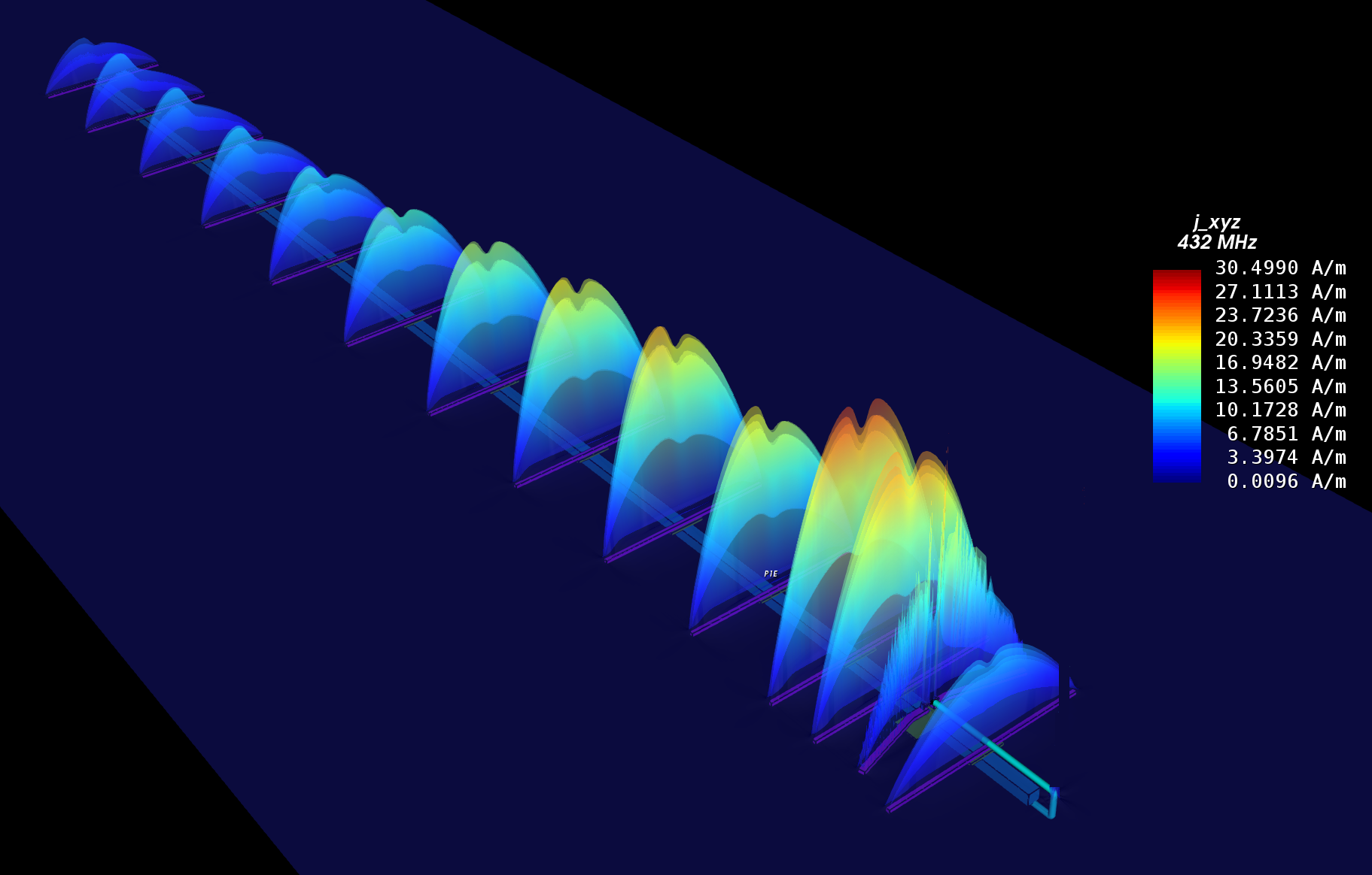
Looking at the power flow diagram, we also note somewhat asymmetric distribution:
Balun, but how to do that?
That example shows: balun matters! The goal is to have a purely unbalanced signal on the coax, with the coax shield at ground potential towards the transceiver, so that the coax doesn’t radiate and has no impact on pattern or matching. This is what we will investigate now, by adding a balun to the simulation models.
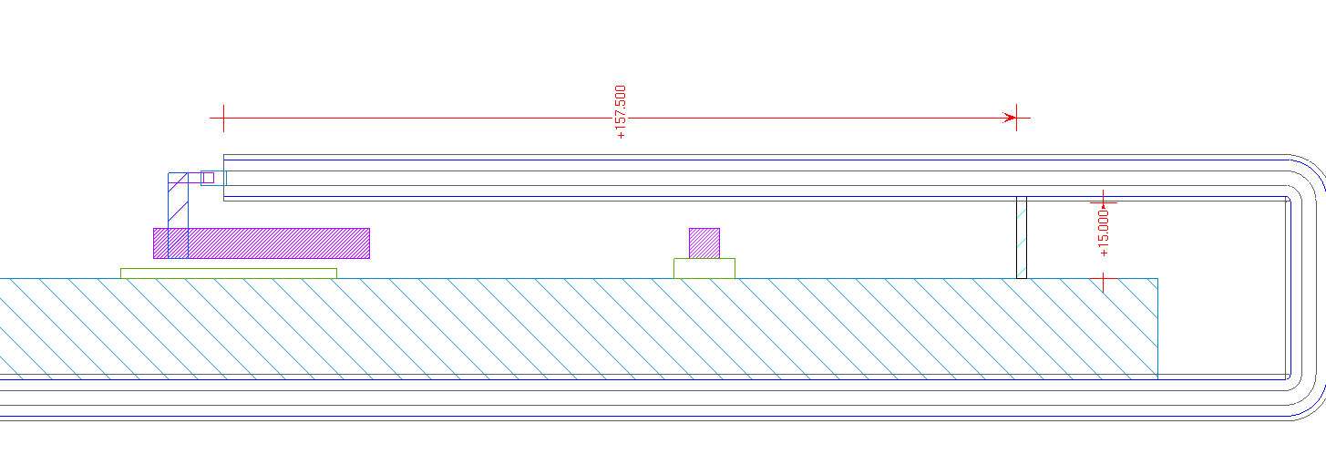
One first step is to create a defined connection from the coax shield to the antenna boom at lambda/4 distance from the feed. The boom is our local ground for the desired differential excitation. So we want to short the common mode signal to that local ground, so that we have an open for common mode at the dipole.
But what is lambda/4 in this situation? Many build reports show measurements where the coax itself is tuned to lambda/4 for signal running inside the coax, using inductive or capacitive coupling to the coax on a lab testbench. But that is not what common mode signals “see” in the actual antenna: the actual common mode conductors are coax (center and shield in parallel!) with the boom as the second conductor (return path). This means common mode does not care about the dielectric inside the coax, and we have mostly an air situation with eps_r=1. Design length for that lambda/4 distance is free space wave length.
In simulations shown below, mechanical length is 157mm for the coax plus 15mm vertical of the boom connection. This was simulated using different coax dielectrics, eps_r=1.38 for air foam and eps_r=2.1 for teflon cables, and results for both coax types were almost identical for both return loss and pattern.
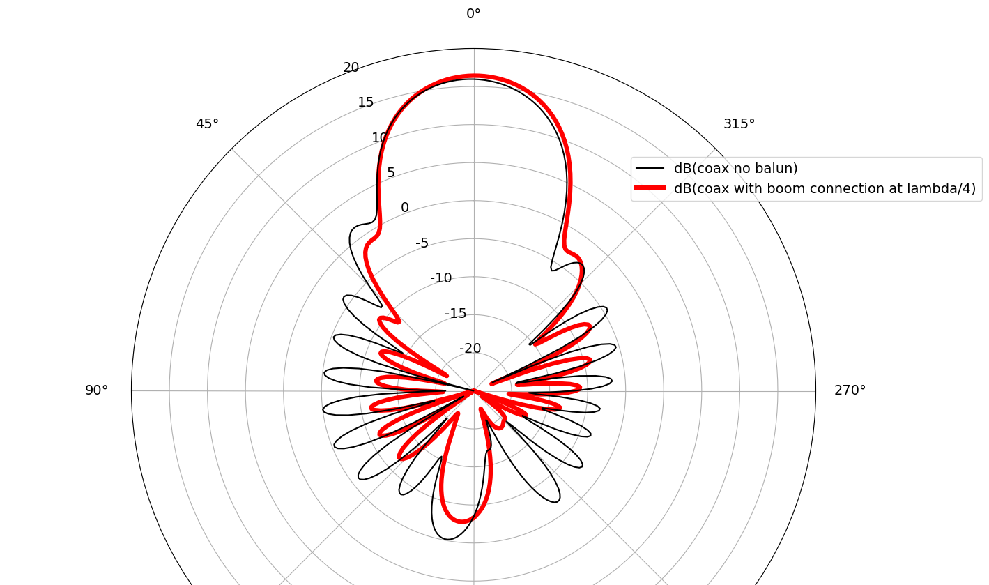
Most sidelobes in the azimuth pattern are reduced by at least 5dB when adding that ground that connection:
Somewhat less difference in the elevation pattern side lobes:
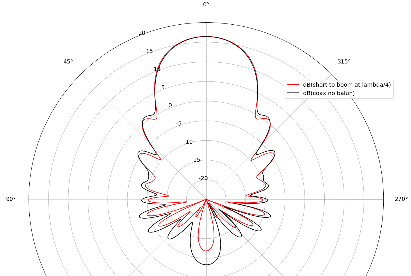
This is an improvement, but not as much as expected. It seems that the simple common mode short isn’t enough to get back to the “ideal” pattern.
Ferrite at feed
DG7YBN suggested a ferrite near the feed, to further suppress common mode. In initial simulation, that method can restore the good pattern, even without the lambda/4 to the boom. However, to reduce losses from the ferrite we combine both methods, the low loss lambda/4 short and the possibly lossy ferrite.
In simulation, we model the ferrite as µr=150 with really large magnetic losses (µr”/µr’=1). These losses are a best guess from the ferrite data sheet, but might be pessimisitic.
Antenna matching is fine as before, no relevant change. Simulated gain and antenna efficiency of >90% are fine, so we don’t have an issue from loss in the ferrite.
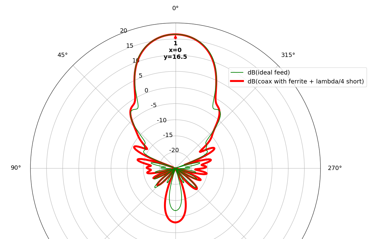
In the azimuth pattern, side lobes and back obe are slightly worse than results with the ideal feed, but much better than other versions of the coax feed.
For the elevation pattern, we are close to the ideal feed.
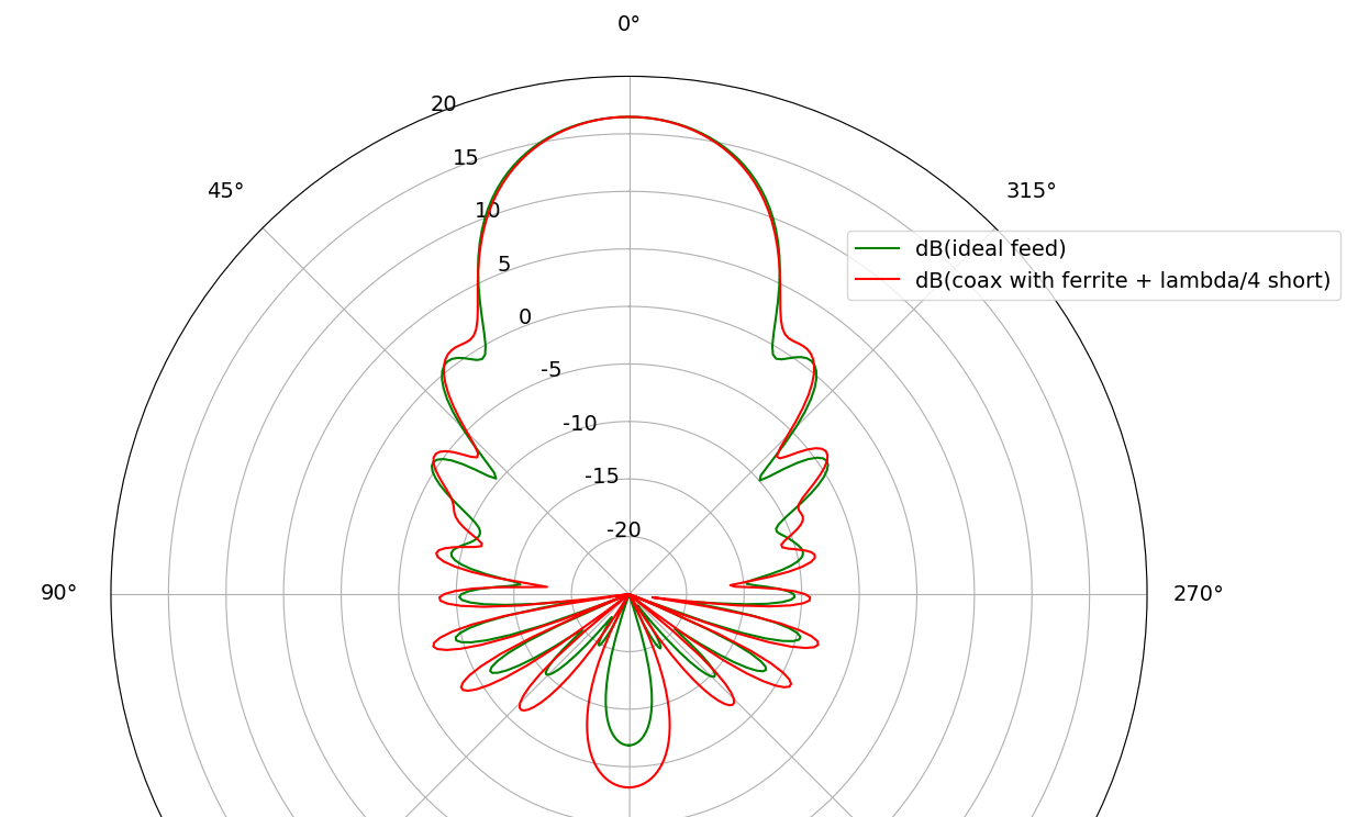
For the back lobe, simulations show -8 dBi which means 23 dB F/B ratio. That is worse than initially designed by DG7YBN, and the worst part in the azimuth pattern. But looking at the elevation pattern, we have many other side lobes there which are only 25dB down from the forward direction. The question is if it makes sense to optimize that one backside direction … to be discussed!
Practical implementation
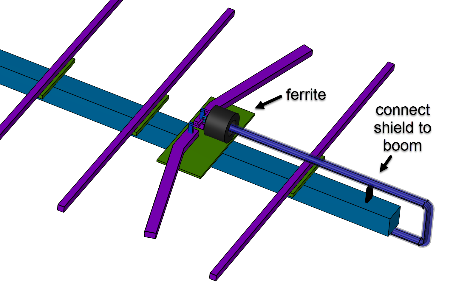
The practical implementation of that feed with balun is shown in the photo below.
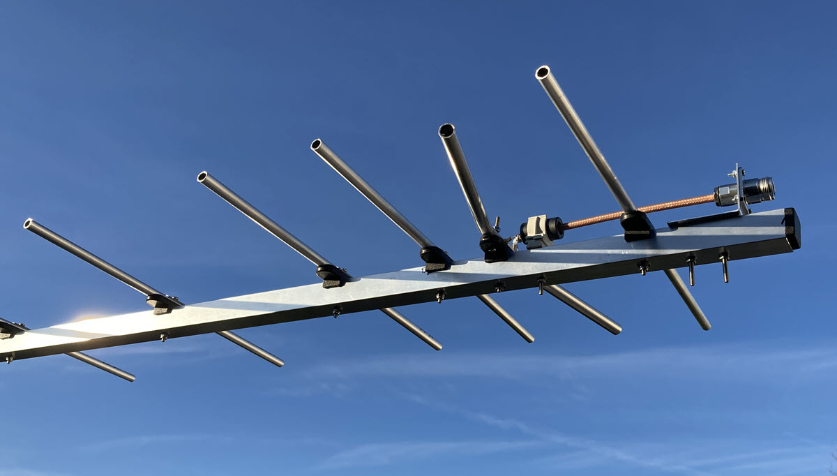
Two antenna samples were built with feed dimensions and feed angle from simulation. VNA measurement showed excellent VSWR < 1.15 at 432.2 MHz for both samples, without any tuning.
Disclaimer: The entire antenna design is (c) DG7YBN. If there is any misunderstanding or mistake in the simulation report and documentation here, that is my mistake. Don’t hesitate to contact me if you spot mistakes or have any ideas for improving the model.