Co-simulation of layout (EM) and circuit components (model based) is important for most circuit designs today. The ADS workflow to perform this task has come a long way, starting from all manual dissection and recombination in the early days and progressing to the fully automated workflow using RFPro. Let’s have a look at this workflow evolution!
The seemingly simple task …
The task description sounds simple: remove discretes from layout and replace them by ports, run EM simulation of the resulting layout-only multiport, then use circuit simulation to reconnect the circuit components with multiport EM results.
Long ago when this was done all manually, it was a tedious and error prone process: dealing with a large number of ports in EM and reconnecting them properly is difficult. Introduction of look-alike symbols instead of black box EM data helped a lot to assign ports properly, but it remained a time consuming work to do all that manually.
The second challenge is visulization of currents and antenna patterns: when components are replaced by ports, viewing the “raw” EM simulation output is meaningless. To overcome this, Keysight had introduced the “EM Circuit Exitation” add-on which can be used to calculate voltage and current at all ports for true visualization of co-simulation results.
Before looking at the new workflow using RFPro, let’s look at co-simulation using the traditional ADS emSetup workflow.
Co-Simulation using emSetup workflow
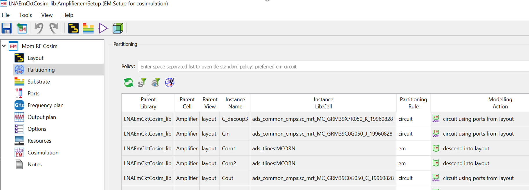
When ADS introduced automated cosimulation setup in ADS 2014, this simplified the workflow a lot: instead of manually replacing and reconnecting discretes, all required intermediate files (layout with ports instead of discretes, schematic to reconnect everything) are created by ADS with just a few mouse clicks. The only task required by the user is to check partitioning rules, i.e. make sure that layout vs. schematic representation is detected as desired. It is possible to override rules manually if desired, i.e. to use a schematic model even for circuit parts that have a layout representation and would be auto-detected as “EM” elements.
When generating the co-simulation data from emSetup, resulting views are generated in the ADS library:
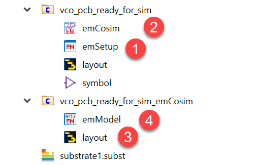
The emCosim view is what we include in schematic simulation to represent the combined EM + circuit result. This is a data container to hold results, similar to emModel for “normal” EM results. In addition, an intermediate cell is created with suffix “emCosim” that provides the EM Model with discretes replaced by ports, and the corresponding emModel for that layout.
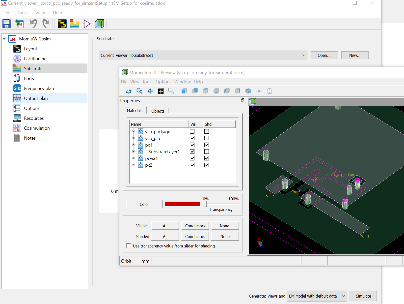
To see the 3D EM preview for a co-simulation model, start from the full layout’s emSetup where “Cosim” is defined. Simply use the EM preview icon as usual. This will show you the EM structure with discretes replaced by ports. Technically, this shows layout + ports found in the intermediate cell layout with suffix “emCosim”, but the way to display that EM preview is through emSetup of the original cell (not the intermediate cell)!
Using RFPro instead of emSetup
ADS now offers RFPro as an alternative workflow that can be used instead of emSetup workflow. That new RFPro workflow is not limited to ADS: it is also available from Cadence Virtuoso or Synopsys Custom Compiler. Here in this appnote, we just look at RFPro from within ADS.
From layout view, use Tools > RFPro > New to create a new rfpro cellview and start the RFPro user interface. Note that RFPro will always “see” your layout data as stored in ADS, and the rfpro cell view provides simulation settings used by RFPro. If you have made changes to your layout, just re-open RFPro and you will see the latest layout. So unlike Keysights stand-alone EMPro 3D simulator, RFPro doesn’t create a “snapshot copy” of the layout, it really works on the exact same data.
Different from Momentum, RFPro can define a simulation model that includes only parts of the layout, by choosing the corresponding nets. No need for creating a layout copy and “cookie cutting”, RFPro does this behind the scenes while working on the full unmodified layout view. This means that any changes to the layout will be reflected in the RFPro model, without manually repeating layout simplifications. This selection of layout pieces for simulation is carried onto new layout iterations automatically , with not manual steps!
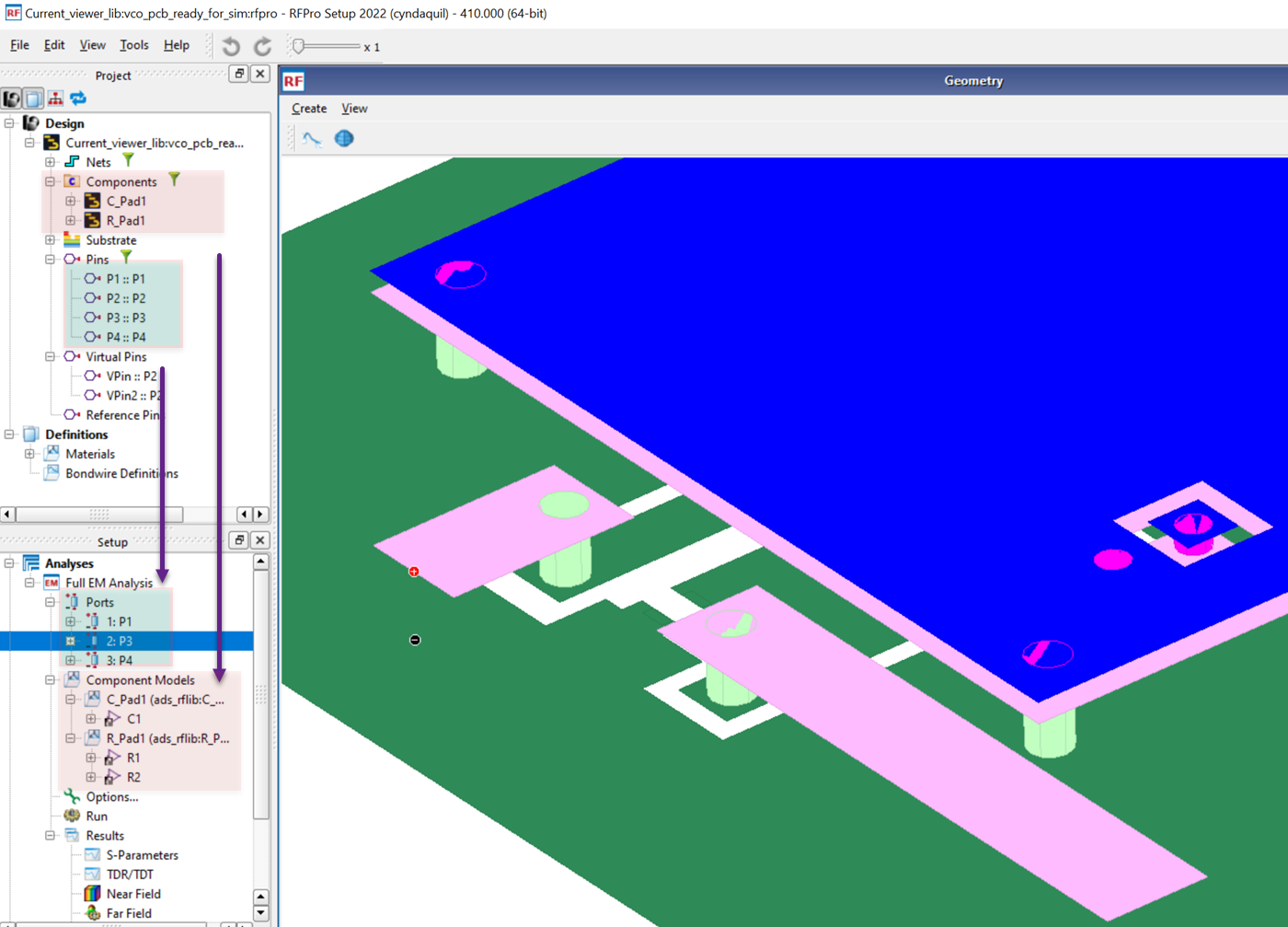
But here, we focus on co-simulation of a full layout: that is quite similar to the emSetup co-simulation discussed before. RFPro shows two tree views: design tree and setup tree. To include ports defined in layout into RFPro EM simulation, use drag & drop from the design tree to the project tree. The same applies to components.
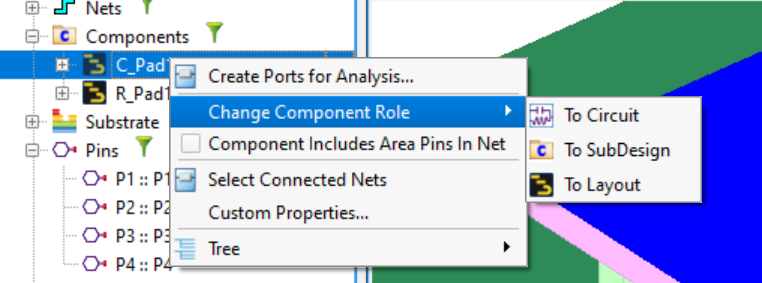
Similar to emSetup cosim partitioning, we can set/override components role in RFPro. In the screenshow below, elements had been detected as “layout” because they have a layout view, but we want them to be included as circuit models.
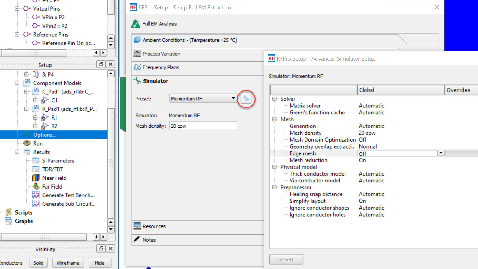
Simulation settings are defined using “Options…” in the Setup tree.
Once simulation settings are defined, we can start simulation using “Run” from the Setup tree. When simulation is finished, we can plot “raw” EM results inside the RFPro user interface, but for co-simulation result of EM part + components we need to bring results back to ADS. There are two options in the Results section of the tree: “Generate Test Bench” if we want to see combined results for this circuit, or “Generate Sub Circuit” if we want to use it as a hierarchical design part.
Below is an example what such a back annotated schematic looks like: It contains the EM multiport data block and components, connected by named nets. For netlisting, this will create the correct connectivity. It doesn’t look very nice if we try to visually check things, we need to trust that connections are correct.
Using this subcircuit or testbench, the combined co-simulation response can be accessed easily for further design and simulation.

Visualizing currents in emSetup co-simulation
To visualize currents propagating in the co-simulated EM structure, it is not enough to just feed one port: we also need to account for all the discrete elements that are connected at schematic level.
For both emSetup workflow and RFPro, we need to enable current storage before starting the EM simulation, and make sure that EM simulation is performed at our frequencies that we want to visualize. This is done using discrete frequency points in addition to adaptive sweep.
Making sure currents are stored
In emSetup flow, there are two places where we need to define current storage to disk for co-simulation: Current storage must be enabled in the Output plan …
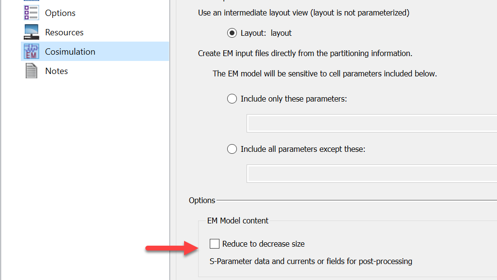
… and in the Cosimulation section, a checkbox must be removed so that currents are stored in emModel also.
Create excitation schematic that provides node voltages & currents
Now that we have EM results with currents stored to disk, we need a multiport excitation that drives all the EM ports (representing components) simulatenously, with the actual voltages and currents.
emSetup workflow
For emSetup workflow, this is implemented by the “EM Circuit Excitation” add-on. Before use, this add-on must be enabled in ADS main window: Tools > App Manager. Once enabled, this adds an “EM” menu to ADS schematic.
For excitation, we need a circuit simulation that provides currents and voltages. A simple AC simulation will do, but of course non-linear simulation is also possible. Only those frequencies can be visualized that agree between EM sweep and circuit simulation, so define the same discrete sweep here that you also used in EM simulation.
After defining the simulation schematic, invoke visulization using the EM > Cicuit Excitation menu item and follow instructions that ADS shows.

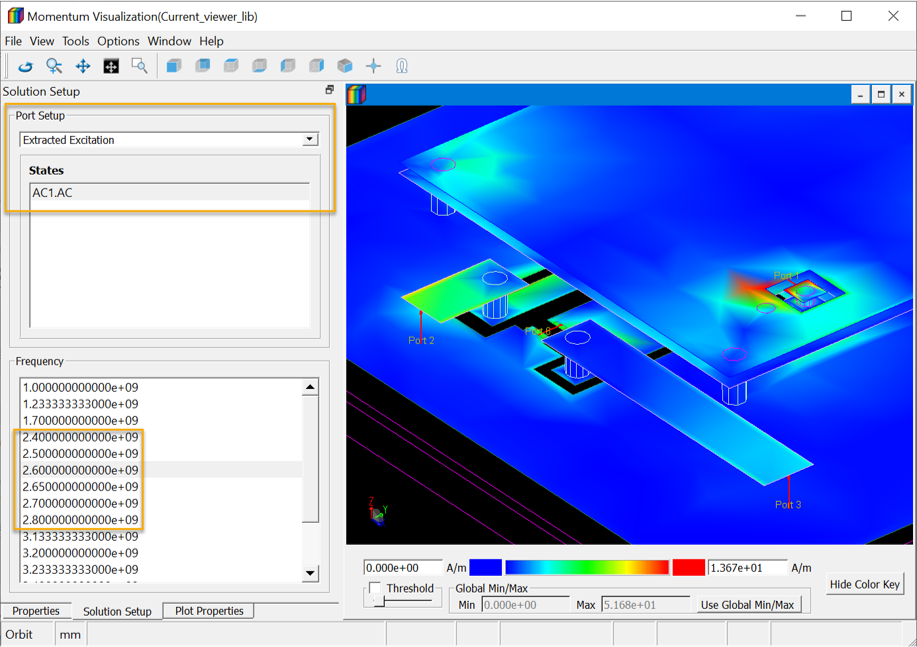
Using this EM circuit excitation, you see an additional port setup type “Extracted Excitation”. This is what you need to use for co-simulated current visualization.
Visualizing currents in RFPro co-simulation
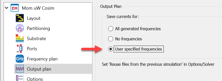
In RFPro, there is only one setting required to save currents for visualization:

Simular to emSetup flow, we need a circuit simulation that calculates node voltage and current for components, which can then drive the multiport visualization. However, for RFPro we don’t need the EM Circuit Excitation feature. Instead, we create a circuit simulation which includes the co-simulation schematic created from RFPro, run simulation and then start RFPro where we select the resulting dataset.
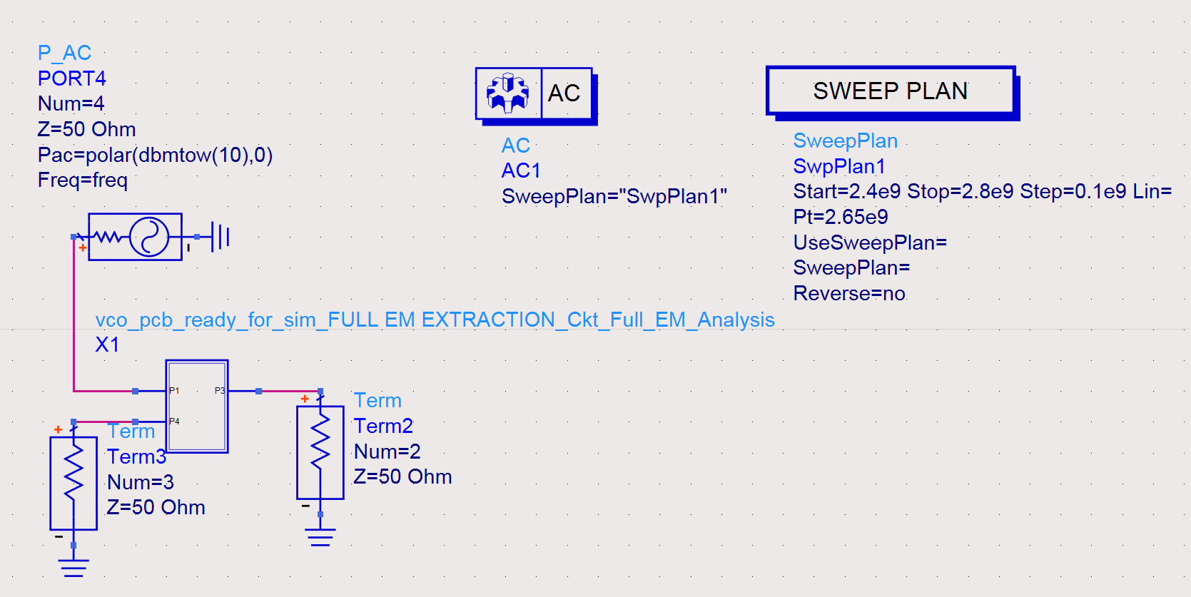
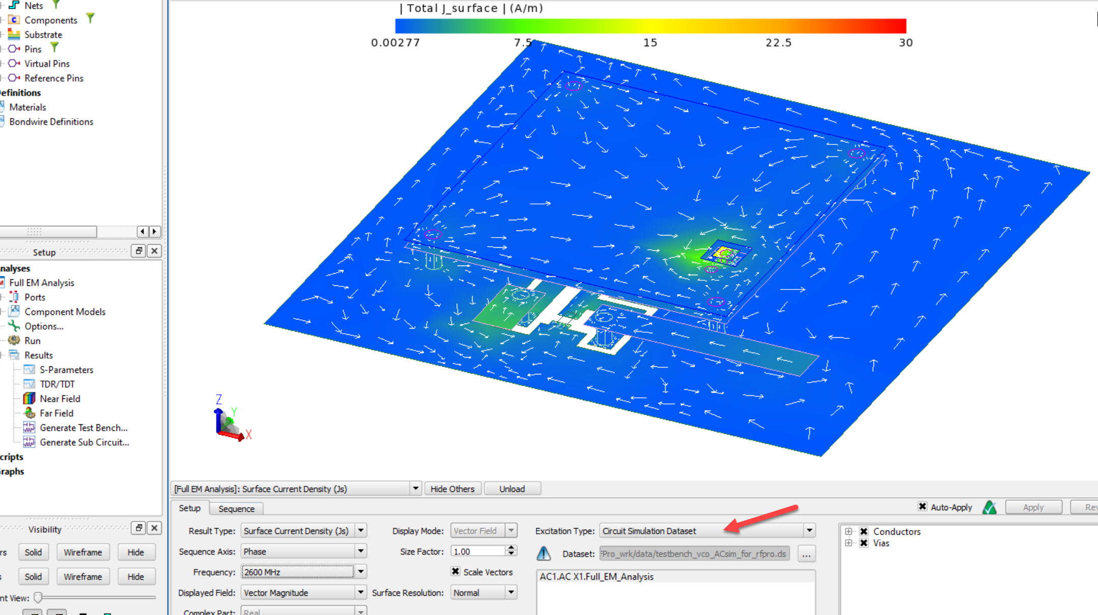
Excitation type is set to “Circuit Simulation Dataset” and points to results from the AC simulation shown above.
Special topic: Including component pads in EM
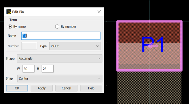
One special topic is component pads: when components are replaced by ports for EM simulation, this usually means that pads defined in the component layout view are removed also. This means that pad effects must already be included in the schematic model, one example for that would be Modelithics library components.
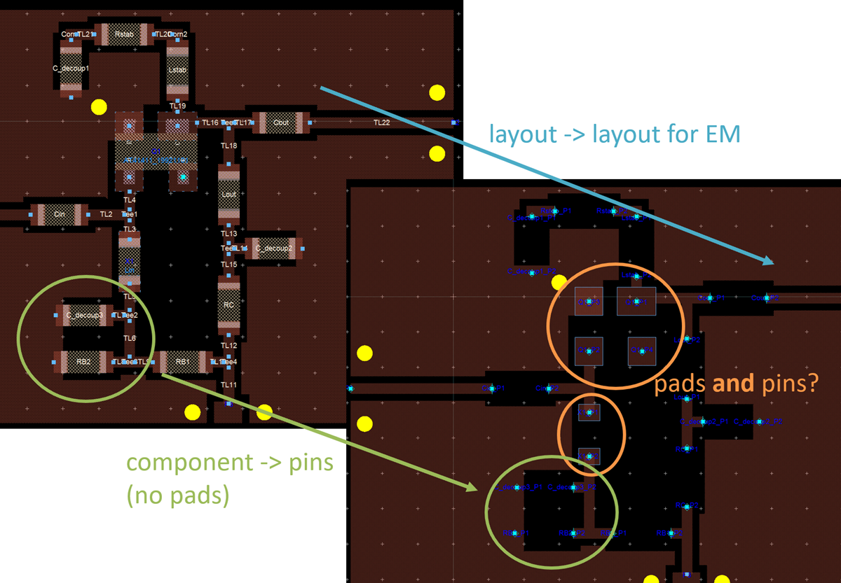
In those cases where pad effects are missing in the circuit model data, but we still want to use automatic co-simulation, the trick/workaround is to define EM area pins with the same size as the pad. This might be already defined that way in a component libary, or otherwise you can define an intermediate cell in hierarchy which defines area pins with proper size in layout view. The screenshot above shows two components (orange circles) where this was done.