In Momentum, ports are usually referenced to some infinite ground plane. That global ground physically connects the reference nodes of all ports, and enables return current between the port grounds. There is an option to create ports with an explicit (-) reference node assigned by the user. I have seen quite some confusion and misunderstanding related to these ports, and when it is safe to use them. Used in the wrong context, you can get some really bad results from differential ports. In this appnote, I will try to resolve some of that misunderstanding.
There are some good uses for ports with an explicit (-) ground reference. Using them for SMD elements, where a device is included as 1-port with (+) on one pad and (-) on the other pad, is not a good idea in most cases. Used in the wrong context, you can get totally unexpected results from differential ports. You really need to understand what these ports physically mean for your model!
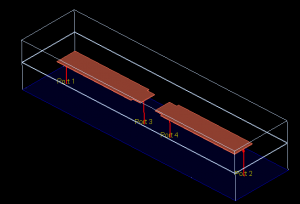
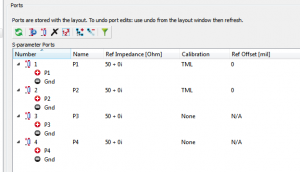
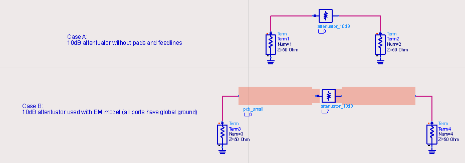
By default, all ports in Momentum have their (-) reference node at the nearest infinite ground place. This is also visualized by the EM preview using arrows to the ground plane. All ports references are physically attached to the same ground plane, and return current can flow there. Shown below is a simple example: a short piece of transmission line with a 2-port component in the middle of the line.
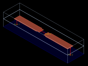
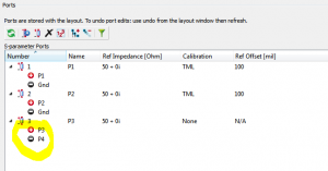
The pin/port configuration can be modified, and multiple pins can ge grouped into one port. If you drag pin4 to the (-) node of port 3, you have defined a differential 1-port where the (+) terminal is at pin3 and the (-) terminal is at pin4. It is important to understand that you have created one port from these two pins. This configuration is visualized by the EM preview, where you now have an arrow between the (+) and (-) node of the one-port device. This model will now provide 3-port EM data, instead of 4-port EM data for the previous configuration.
Are both cases equal? Obviously not. What you can connect in the differential case (one-port device in the middle of the line) is only a series element between the pins. That’s how we defined that differential port. There is no path to ground from pin3/4 and the S-parameters from this EM model will not allow any current to flow from pin3/4 to the ground below.
The normal case (“single ended” or “global ground”) is the general case, where we can connect any shunt or series elements in the middle of the line. We get the full 4-port EM data from the normal case, whereas we get only 3-port EM data for the differential port case. The differential port model is already limited/specialized in what we can connect at the port in the middle of the line: pure series elements.
What can go wrong?
GND example
So what can go wrong if we use differential ports in the wrong context? We will look at two examples. The first example is rather trivial: we connect a “short” to one of the SMD pads. The second example, discussed later in this appnote, uses an attenuator with both series and shunt elements.
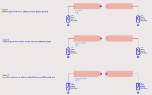
The testbench for the first example is shown below. Case A and B look identical at schematic level, but emModel for case A has two separate ports for the two pads, and emModel B uses one differential port with (+) at one pad and (-) at the other pad.
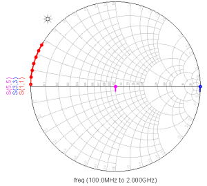
If we look at the simulation results, these are totally different. Input impedance for case A (red curve) shows the expected response: a short circuit at low frequency, with some length of line adding phase at higher frequeny. For case B (blue curve) we see an open circuit instead. Why is that?
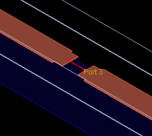
The open circuit for case B is because the (+) terminal of the differential port has no connection to the corresponding (-) reference terminal. No current can flow through the port, and we have an open circuit. The connection of the (+) terminal to the ground symbol seems to create a path to the PCB ground, but it really does not because the differential port doesn’t allow any current flow to that PCB ground. Just look at the port definition in the 3D view again:
The current that goes into the (+) terminal can only exit at the (-) terminal, and the there is no path to the PCB ground. So whatever we try to connect there at schematic level, no current will flow from one of the pads to PCB ground. That’s different from the 2-port case, where each pad has a port with ground reference at the PCB ground, and current can flow between the pads (series) or to PCB ground (shunt).
So what is that case C in the example? It has the emModel with differential port with (+) at one pad and (-) at the other pad, but now, we have connected a ground symbol at both pads. And the results for input impedance is … not an open, not a short, but we see 50 Ohm input impedance! Why is that?
It is because the (+) and (-) terminal of the differential port are now connected to the same node, and current can flow from (+) to (-). We now have an ideal connection between the (+) and (-) terminals, e.g. we have connected both pads and see 50 Ohm load at the output of the line. This is the same as creating a wire between the two terminals of the differential ports. The “ground” symbol looks strange here, but remember: we can’t have current at the differential port to global PCB ground. We can only have “series” current that goes into one pad and exits at the other pad.
Hopefully, this example has shown that differential ports for SMD are easily mis-used and misinterpreted, and we should better use ports with global ground to avoid such misunderstanding and confusion.
Attenuator example
Now let’s look at an example where we connect a model that has both series and shunt elements. In the middle of the EM simulated line, we connect a 10dB attenuator.
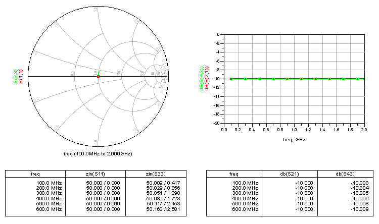
Everything looks correct when we compare the stand-alone attenuator with the “normal” co-simulation case where all ports use “global ground”. Results are what we expect, with some small parasitics introduced by the layout. No surprise here.
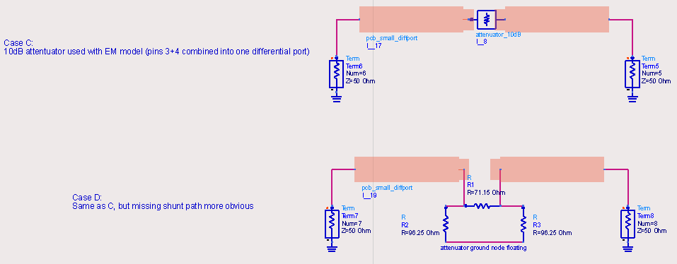
Now let’s see what we get for the differential port case. Now, the attenuator 2-port network is connected between the (+) and (-) terminal of the differential port. Using the layout-look-alike symbol, this looks the same at schematic level. However, meaning and results are different as we will see …
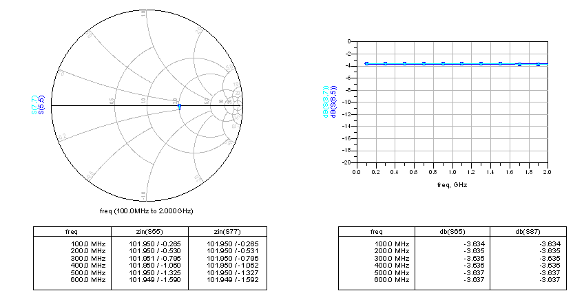
By grouping pin 3 and 4 into one differential port, instead of 2 global ground ports, we have changed the possible current flow. With the differential port, only series current can flow between pin 3 and 4, and any shunt elements connected there will have no effect. For our attenuator, that has a large impact on results. Instead of 50 Ohm input impedance and 10dB insertion loss, we now have 102 Ohm input impedance and 3.6 dB insertion loss.
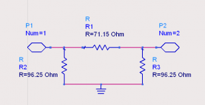
Let’s try to understand these values, by looking at Case D in the schematic above. That shows the resistors of the attenuator connected to the lines, with the shunt path (ground) disconnected. Then, the attenuator behaves like a series element with 71.15 Ohm || (96.25 Ohm + 96.25 Ohm) = 52 Ohm plus 50 Ohm load at port 2 = 102 Ohm input impedance. Totally different from what we wanted to simulate, because the attenuator’s ground connection is missing. The differential port in the EM model has cut off that ground path for the device connected there.
What have we learned?
There are some good uses for ports with an explicit (-) ground reference. Using them for SMD elements, where a device is included as 1-port with (+) on one pad and (-) on the other pad, is not a good idea in most cases. It will work if a pure series impedance is connected, and give inaccurate or even nonsense results in all other cases.This is not a tool limitation of ADS or Momentum, it is just applied physics: If you restrict the EM model port current to pure series current between (+) and (-), there is no path to other grounds and no shunt current can flow when using the EM model results with devices that require shunt currents.
For devices that have both series and shunt path, make sure that your port definition allows shunt current to flow to the physically correct ground location.

