In this application note, we will look at the basics of AEL programming for customized layout (“artwork”) and how to include that in your ADS project.
Download example (ADS 2015.01 workspace, 11kB)
Overview
In many cases, layouts can be created from built-in layout elements or by stretching polygons, as shown here. However, some more complicated layouts cannot be created this way. An example would be a spiral inductor with variable number of turns. This type of layout can be created by writing code in the ADS programming language AEL.
The basic steps needed to create and use “coded” layout definitions are:
- Write AEL code that reads the cell parameters and draws the artwork
- Create a cell layout view and configure it to use the AEL code for drawing
- Configure the ADS library to load the AEL code when the library loads.
A workspace with all examples is available for download at the end of this document.
Getting started – draw a rectangle by AEL code
To get started, we will create a simple layout that has no parameters. A cell will be configured to call our AEL drawing code, and the ADS library will be configured to load the code. Later in this document, we will extended the example to support scalable artwork using cell parameters.
Step 1: Write AEL code that draws the artwork
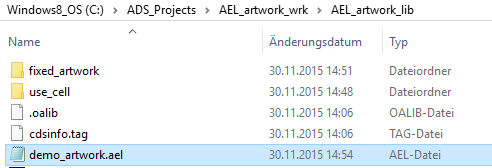
For our first example, create a new workspace AEL_artwork_wrk. In the ADS workspace directory, go one level down into the library directory AEL_artwork_lib and create a file “demo_artwork.ael” inside the library directory.
… open it with a text editor and add this AEL code to the file:
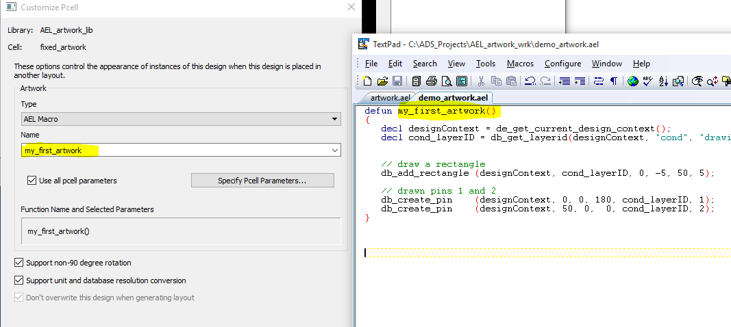
defun my_first_artwork()
{
decl designContext = de_get_current_design_context();
decl cond_layerID = db_get_layerid(designContext, “cond”, “drawing”);
// draw a rectangle
db_add_rectangle (designContext, cond_layerID, 0, -5, 50, 5);
// drawn pins 1 and 2
db_create_pin (designContext, 0, 0, 180, cond_layerID, 1);
db_create_pin (designContext, 50, 0, 0, cond_layerID, 2);
}
This is our first simple artwork code, to draw a rectangle from (x=0, y=-5) to (x=50, y=5) on layer “cond”, with pins on both sides. Pin 1 routing direction is 180 degree (left), pin 2 routing direction is 0 degree (right). Only a few lines of code, no proper handling of units etc … We will refine this later, but for now this is good enough to show the workflow.
Step 2: Create a cell layout view and tell it to use the AEL code for drawing
Now, create an empty layout view for a new cell. We will tell ADS to draw this cell using our code, instead of using artwork from the layout editor. The only purpose of the layout view is to reference our AEL code. In ADS 2015, this is set with File > Customize PCell. Change the type from “Use this layout” to “AEL Macro” and enter the name of the function (not the filename).
After creating a file with AEL code, and telling ADS what function to use for drawing, we need to actually load the code into ADS.
Step 3: Configure the ADS library to load the AEL code when the library loads
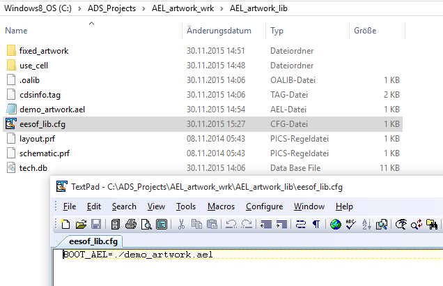
For such custom AEL artwork, the best method is to automatically load the AEL code when the library is loaded. ADS always checks for a file “eesoflib.cfg” in the library directory and is able to execute a “boot” file defined there. We will use that to define our demo_artwork.ael file as the boot file.
Now when the workspace is loaded, our AEL code is loaded and executed. ADS then knows about our function definition “my_first_artwork” and is able to use that for drawing the cell.
To force re-loading the workspace (including our code), we can use the file history from the menu: File > Recent Workspaces. Always do this when you have changed the code, to re-load the latest code version. It is not necessary to close the project before re-loading it.
Testing the artwork cell
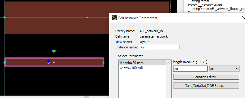
To see if our custom artwork works, we need to place our custom artwork cell into another layout. In the screenshot, custom artwork cell “fixed_artwork” is placed into a new cell called “use_cell”. It should now be drawn – or we should see an error message if there is a mistake in our code.
Location (x=0, y=0) in our code is the insertion point of the cell, and a rectangle of 50 units length and 10 units width is drawn, with the units as defined in the workspace. Next, we want to add support for cell parameters, and a proper handling of different length units.
Use cell parameters
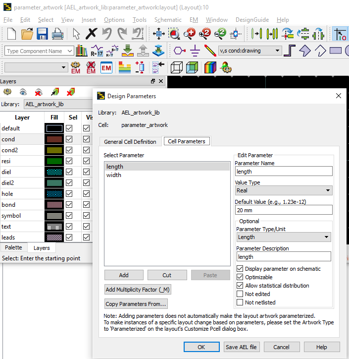
Create a new cell and use File > Design parameters to add length and width parameters. In the screenshot below we have 20mm for the length and 2mm for the width.
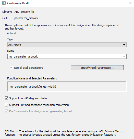
Now use File > Customize PCell to set the artwork type to “AEL Macro” and enter the name of our new parameterized artwork function. In the screenshot below, have a look at the brackets ( ) with parameters that are now passed to the artwork function. Order matters, so in our code we need to read these values with the order defined here!
Here is the modified artwork code, extended to read and use the two parameters:
defun my_parameter_artwork(length, width)
{
decl designContext = de_get_current_design_context();
decl cond_layerID = db_get_layerid(designContext, “cond”, “drawing”);
// get mks to user units conversion factor
decl mks2uu = db_get_mks_to_uu_factor(designContext);
length = length * mks2uu;
width = width * mks2uu;
// draw a rectangle
db_add_rectangle (designContext, cond_layerID, 0, -width/2, length, width/2);
// drawn pins 1 and 2
db_create_pin (designContext, 0, 0, 180, cond_layerID, 1);
db_create_pin (designContext, length, 0, 0, cond_layerID, 2);
}
You will notice the extra lines of code with the unit conversion. This handles the conversion of different user input (mm, mils, microns, …) to the internal user unit. Just make sure that you convert all the dimension variables required for drawing.
That’s all for our simple AEL artwork example. Some references to more detailed information, and for debugging your code, are included below.
Learning more about AEL artwork functions
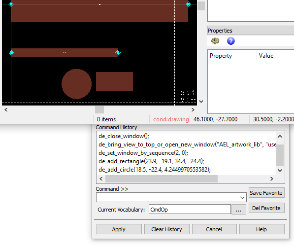
One very nice way to learn about AEL drawing commands is to open the ADS command line window. From the ADS main window, go to Tools > Command Line … and you will get a small extra window that starts logging the AEL command for your actions in ADS. Start drawing and you will see what AEL commands are used.
Another great resource is the ADS online help, chapter Design Tools > AEL. Here you can find instructions and command reference documents. And if you are looking for more details on a function that you had seen in the log file, the Search tab will be really useful.
Debugging AEL code
Yes, you can debug AEL code to find mistakes in your code. There is a real debugger that can be started by inserting a line
start_debugger();
into your code. Using the debugger is described in ADS help chapter Design Tools > AEL > Debugger.
As an alternative, you can print debug code to the console using fputs(). A useful formatting function in this context is identify_value () to convert various ADS data types to a string representation.
fputs(stderr, “Finished step 1”);
fputs(stderr, strcat(“Calculated results = “,identify_value(result)));
This error console output will be shown automatically if you run ADS on Linux.
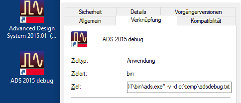
For ADS on Windows, you will need to tell ADS to dump the output to a file. ADS for Windows will then display an additional console window with the error output. To start ADS for Windows in this debug mode, you need to add start parameter “-d” and the path+filename of the debug log file to create.

