This application note investigates the effect of dummy metall fill on the performance of a 60 GHz balun. The balun design is described in this application note.
Dummy metall fill is used to fulfill metal density design rules. If possible, such filler is blocked underneath and near inductors and transformers, to avoid a reduction in performance. But the question is: how much effect is that, and what filler distance is “safe”? In this document, we investigate the effect of different filler placements on a balun.
In many EM simulations, the electrical effect from fillers is considered small, and they are removed from EM simulation to speed up simulation. But here, to investigate the filler effect, we need to include them and this results in models with >100k metal polygons. Such a large model would be very time- and memory consuming for Method of Moments (MoM) or Finite Elements (FEM) solvers.
Empire XPU was selected for this simulation, because Empires FDTD method scales very efficiently for large number of mesh cells. Empire XPU features very high processing speed and enables models with large number of metal polygons, in reasonable time, with full 3D EM accuracy.
Balun with no dummy metal fill
Baseline simulation for this investigation is the balun without any dummy metal fill. This is simulated as a two port circuit, with 50 Ohm at port 1 and 200 Ohm at port 2.
Balun with dummy metal fill
Next, dummy metal was added outside and inside the balun, on all metal layers, with a clearance of ~12µm width. This corresponds to 3 x trace with.
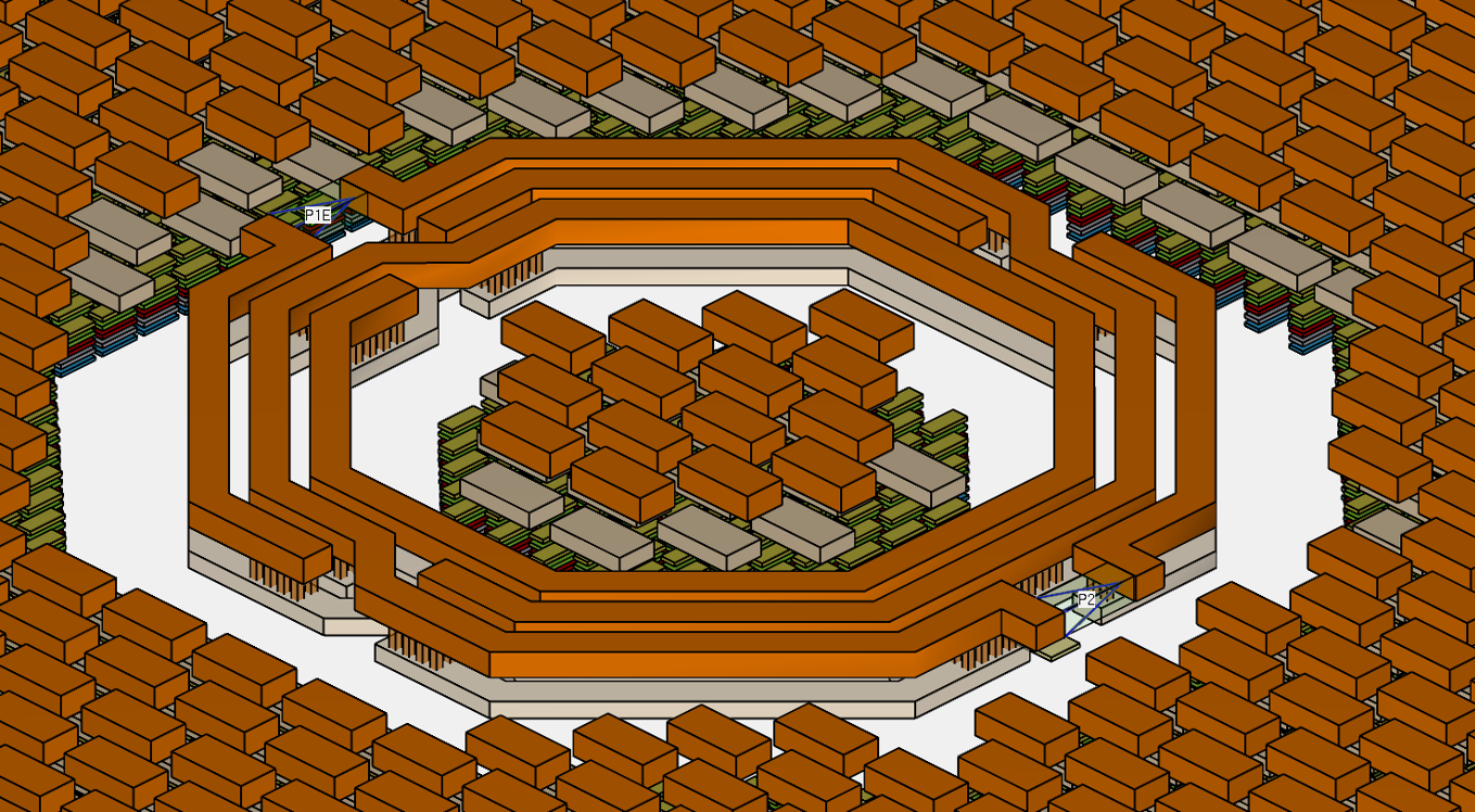
The resulting EM model size is around 130,000 metal polygons. A very dense simulation mesh with 80 MCells was used, so that each dummy fill polygon is meshed with multiple cells, to enable eddy currents and other relevant effects.
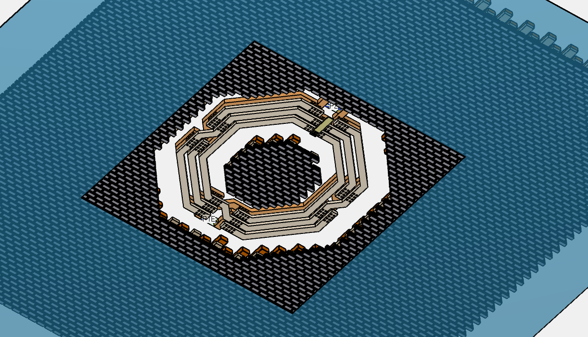
Another model was created with dummy fill only on the outside of the balun. No fillers are placed inside the turns. The screenshot below shows both configurations.
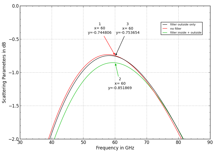
Simulation results with dummy fill
Simulation results show a very small effect if dummy fill is placed only outside the balun, at the distance shown above. When fillers are also placed inside the turns, insertion loss increases by approximately 0.1dB.
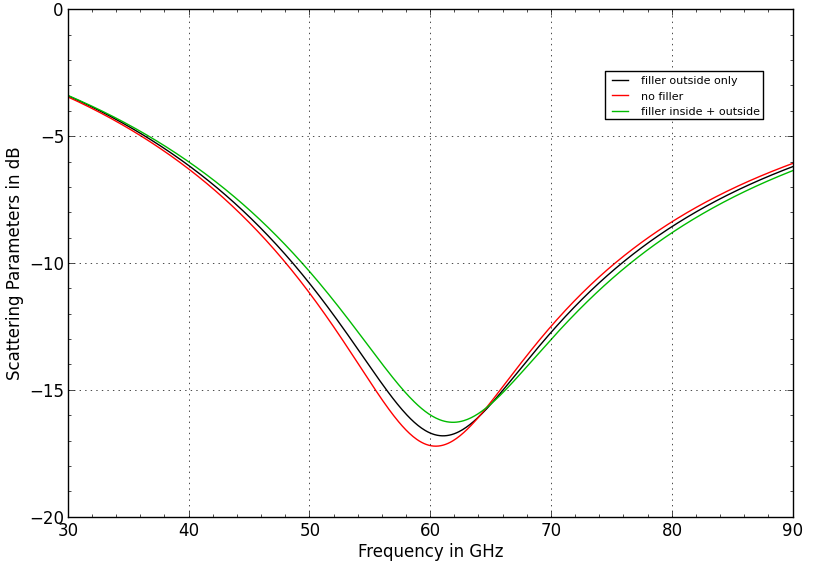
The influence on S11 is rather small in both cases.
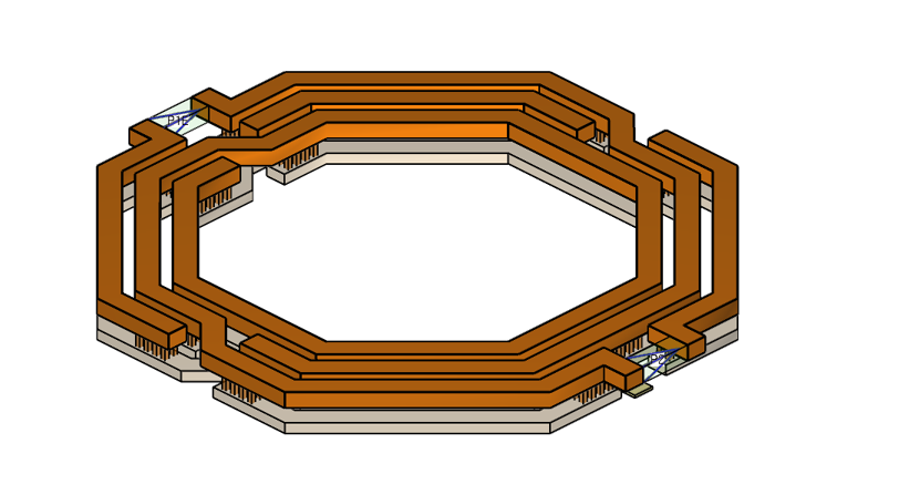
Closed ground ring on Metal1
Dummy fill is expected to have a small influence only, because the metal islands are floating and eddy currents can only form on each small filler polygon. However, a larger influence is expected when adding a ground frame that forms a closed loop around the balun/transformer.
This is investigated next, with a closed metal frame on layer Metal1. Distance from balun to the metal frame is 25µm. The model below shows a view from the bottom side.
Even at this large distance, this ground frame results in some additional insertion loss. This means that we need to pay attention to metal frame distance, or possibly avoid closed loops around inductors and transformers.

What is the physical effect?
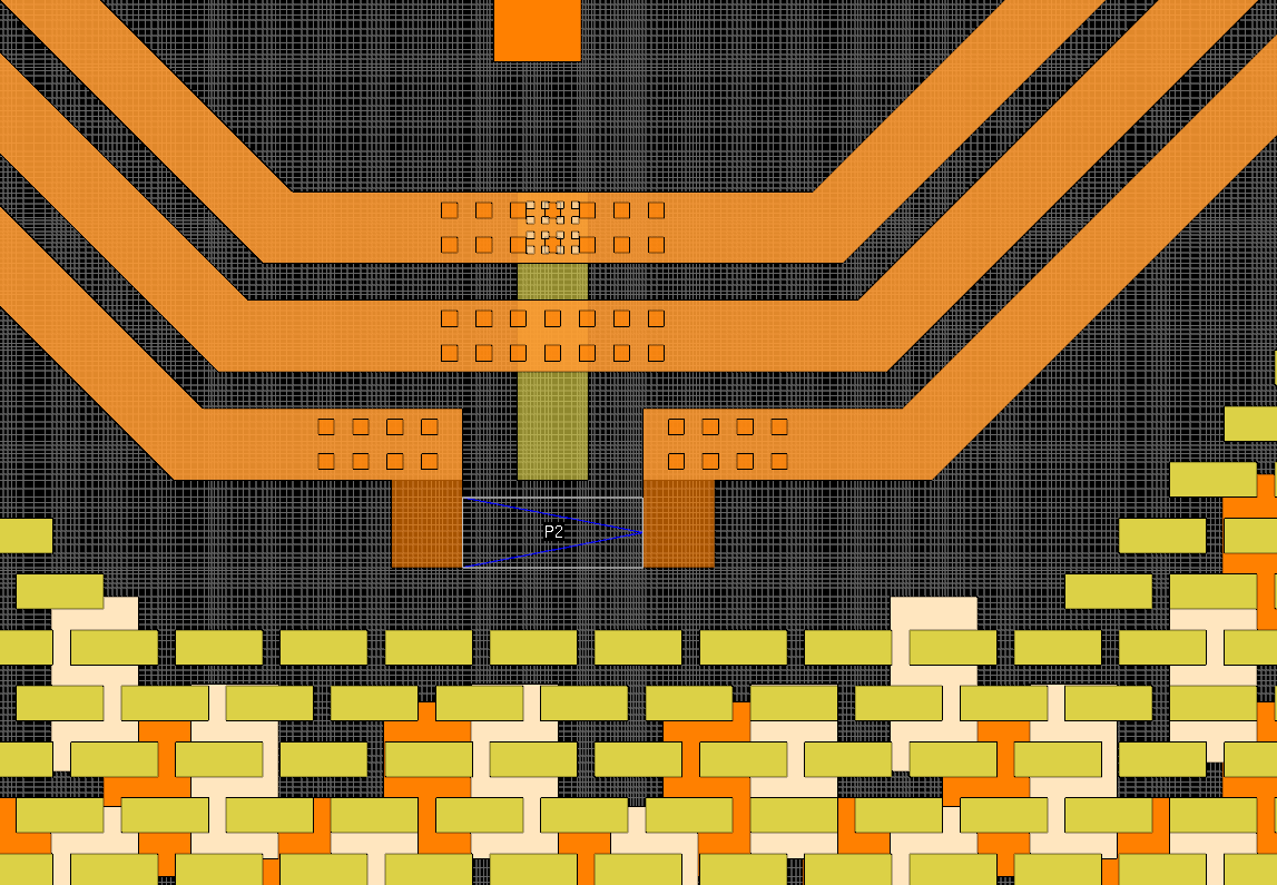
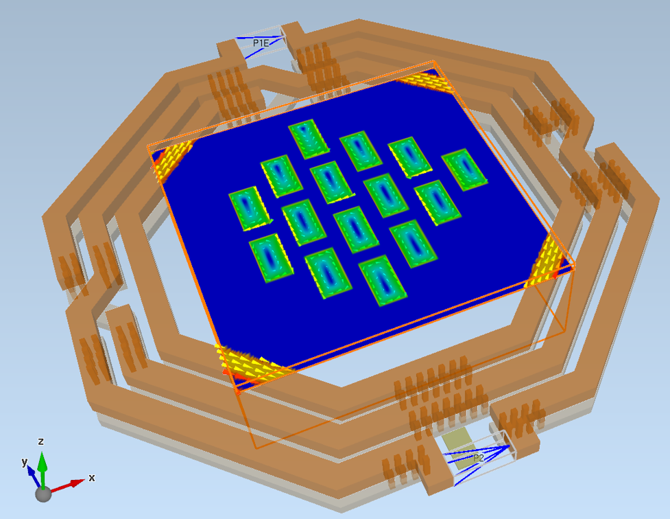
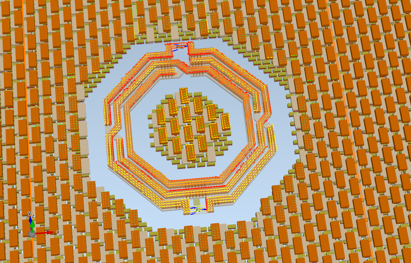
To understand the physical effect causing the extra loss, current density on different metal layers was evaluated.
It can be seen that balun current induces circular eddy currents on each of the isolated filler objects. The partial field plot below shows current densities in the center of the balun. Blue is no current, red is high current, arrows indicate current direction.
And here is another view (arrows only) of currents on layer TopMetal2, showing the decay of eddy currents outside the balun. Click on the picture to see it in full size.
The same behaviour is also seen on the smaller dummy fill on lower metal layers.
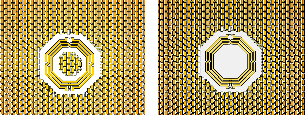
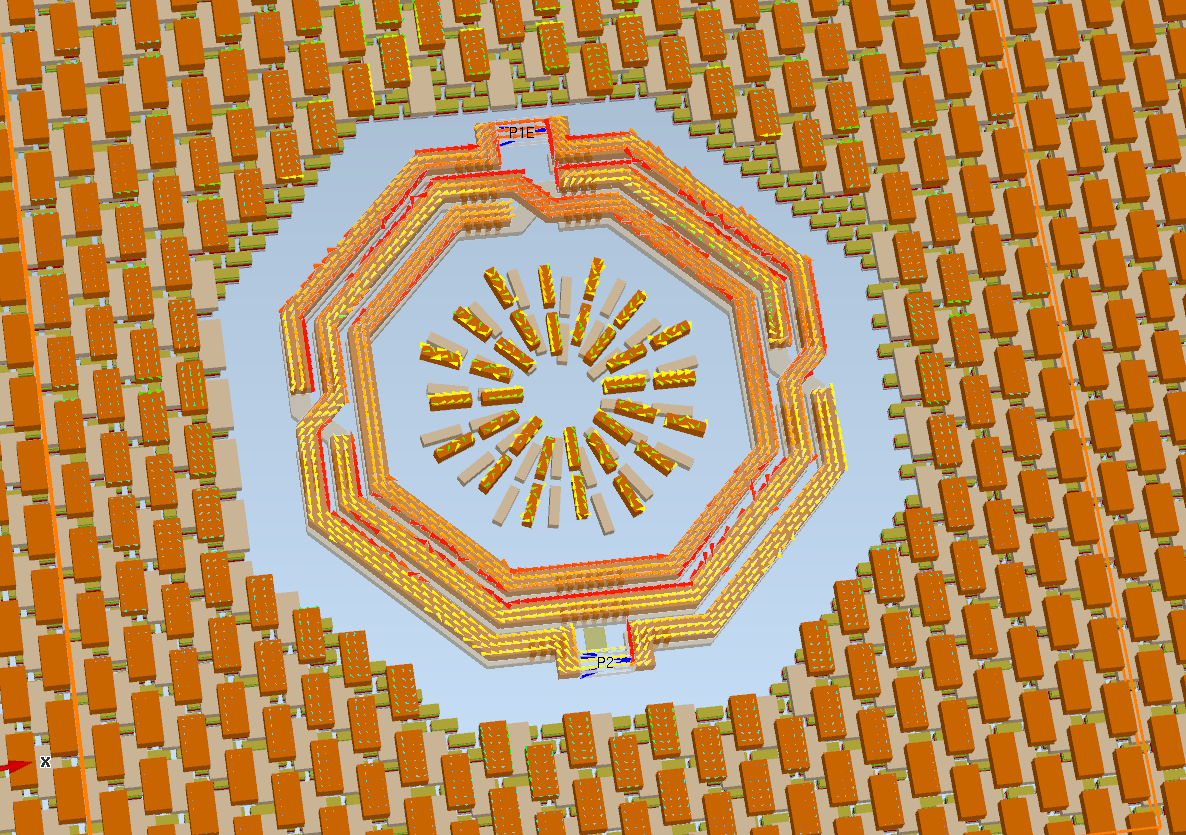
One idea might be to change the dummy fill shape to radial structures, perpendicular to the balun traces, similar to a patterned ground shield. However, it’s not that simple. Eddy current for such small “islands” is not very sensitive to orientation and is also seen on radial structures.
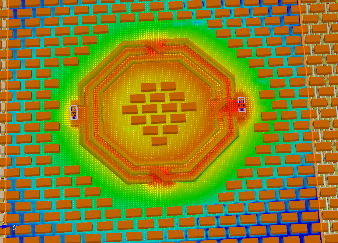
The strong decay of filler currents outside the loop is no surprise if we look at magnetic field (H field) distribution. Again, blue is no field, green is medium field and red is high field intensity. Scale is log 70dB.
Summary
The effect of dummy metal fill on this 60 GHz balun has been investigated by EM simulation. It was found that the combined effect of metal fillers and ground frame can cause a relevant degradation of performance, even for this reasonable spacing. The filler effect could be reduced by removing fillers inside the balun, or in general: remove it in regions of high magnetic field, to reduce eddy currents in the dummy fill.
For simulation of such models with many polygons, Empire XPU provides a fast and accurate full 3D EM solution. Simulation time for the very densely meshed models shown here with 130,000 metal objects was approximately 2 hrs on a Core i9 desktop computer and required less than 4 GB of memory.